
Circularly polarizing plate, optical film and image display

A circularly polarized light, thin film technology, applied in optics, optical components, polarizing components, etc., can solve problems such as poor productivity and darkened display

Inactive Publication Date: 2007-03-21
NITTO DENKO CORP
View PDF15 Cites 15 Cited by
  • Summary
  • Abstract
  • Description
  • Claims
  • Application Information

AI Technical Summary

Problems solved by technology

However, in the former case, the transmittance of white display is also lowered at the same time as that of black display, and there is a problem of darkening the display.
In addition, the latter requires replacement of the process, and there is a problem that productivity deteriorates
[0008] Especially in the multi-domain panel of the circularly polarized light mode described above, where the circularly polarized light sheet is used as a transmission filter, a circularly polarized light sheet with high transmittance and high polarization degree is more and more required. more clearly visible problems

Method used


Image

  • Circularly polarizing plate, optical film and image display
  • Circularly polarizing plate, optical film and image display

Examples


Embodiment 1

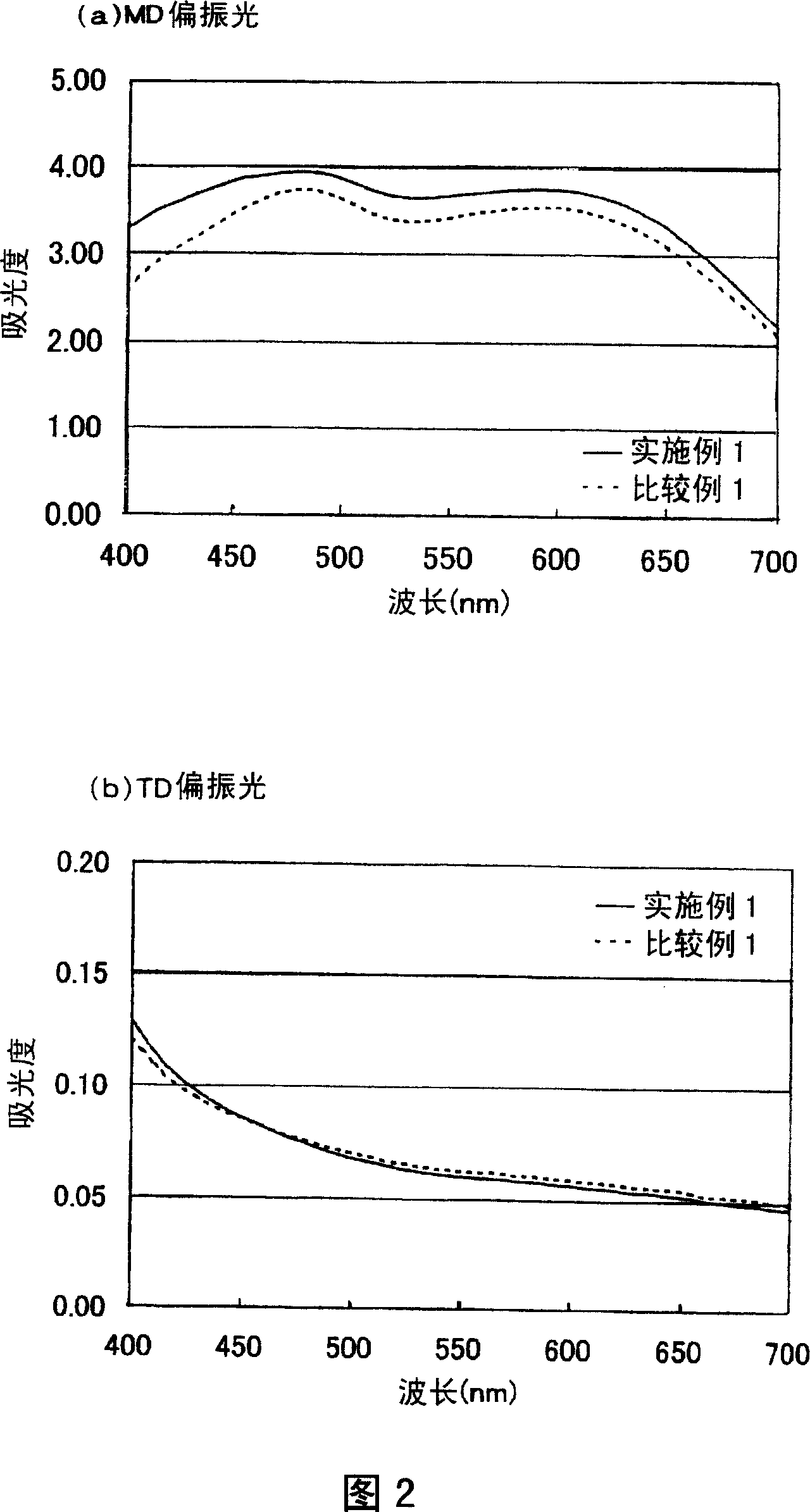
[0169] The scattering-dichroic absorption composite polarizer and retardation plate 3 (1 / 4 wavelength plate) obtained above were bonded together via an acrylic adhesive to prepare a circular polarizer. The stretching axis of the absorbing composite polarizer and the stretching axis of the 1 / 4 wavelength plate are bonded at an angle of 45°.

Embodiment 2

[0171] In Example 1, a circular polarizing plate was produced in accordance with Example 1 except that the retardation plate 4 (1 / 4 wavelength plate) was used instead of the retardation plate 3 (1 / 4 wavelength plate).

Embodiment 3

[0173] In Example 1, a circular polarizing plate was produced in accordance with Example 1 except that the retardation plate 5 (1 / 4 wavelength plate) was used instead of the retardation plate 3 (1 / 4 wavelength plate).


PUM


Abstract

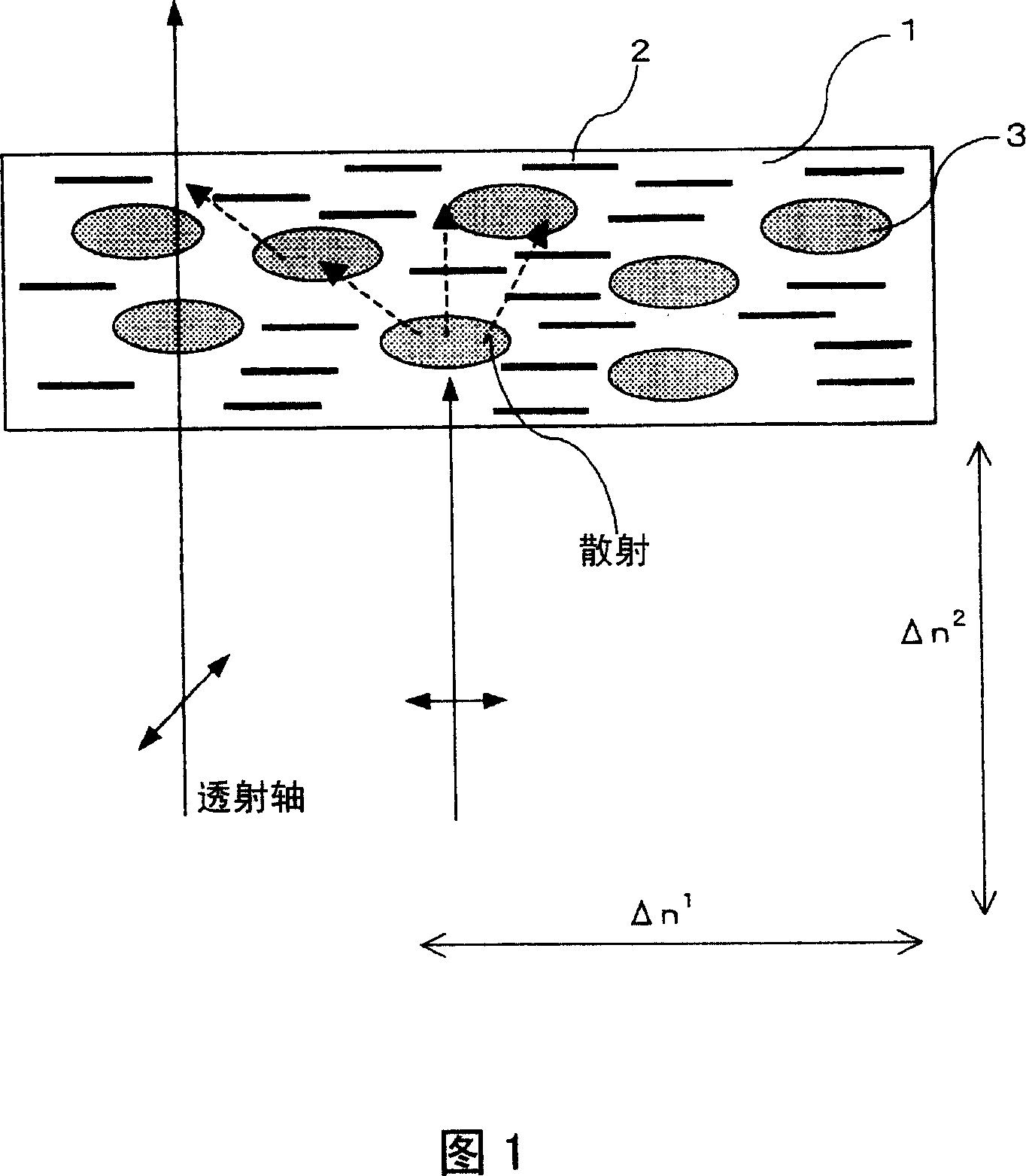
A circularly polarizing plate comprising a scattering-dichroic absorption compound polarizer composed of a film dispersed with micro-regions, and a quarter-wavelength plate composed of one or a plurality of phase difference plates that are laid in layers in a matrix formed of translucent resin containing iodine based light absorbing material. Such a circularly polarizing plate exhibits high transmittance and high degree of polarization and can suppress unevenness of transmittance in the case of black display.

Description

technical field [0001] The invention relates to a circular polarizer. Moreover, it is related with the optical film which used this circular polarizing plate. Furthermore, it relates to image display devices such as liquid crystal display devices, organic EL display devices, CRTs, and PDPs using the circularly polarizing plate and the optical film. Background technique [0002] In watches, mobile phones, PDAs, notebook computers, monitors for personal computers, DVD players, TVs, etc., liquid crystal display devices are rapidly expanding into the market. A liquid crystal display device visualizes a change in a state of polarization due to opening and closing of liquid crystals, and uses a polarizer based on this display principle. In particular, high-brightness and high-contrast displays are increasingly required for applications such as TVs, and polarizers that are brighter (high transmittance) and higher contrast (high degree of polarization) have also been developed and...

Claims


Application Information

Patent Timeline
IPC IPC(8): G02B5/30G02F1/1335C09K19/38C09K19/60G02B5/02G02F1/1334G02F1/13363
CPCG02F2001/133541C09K19/60G02F1/1334C09K19/3852G02B5/0242G02F1/133634G02B5/3033G02B5/0257G02F2001/133638G02B5/0278G02F1/133541G02F1/133638G02B5/30G02F1/1335
Inventor 宫武稔二村和典
Owner NITTO DENKO CORP
Learn More