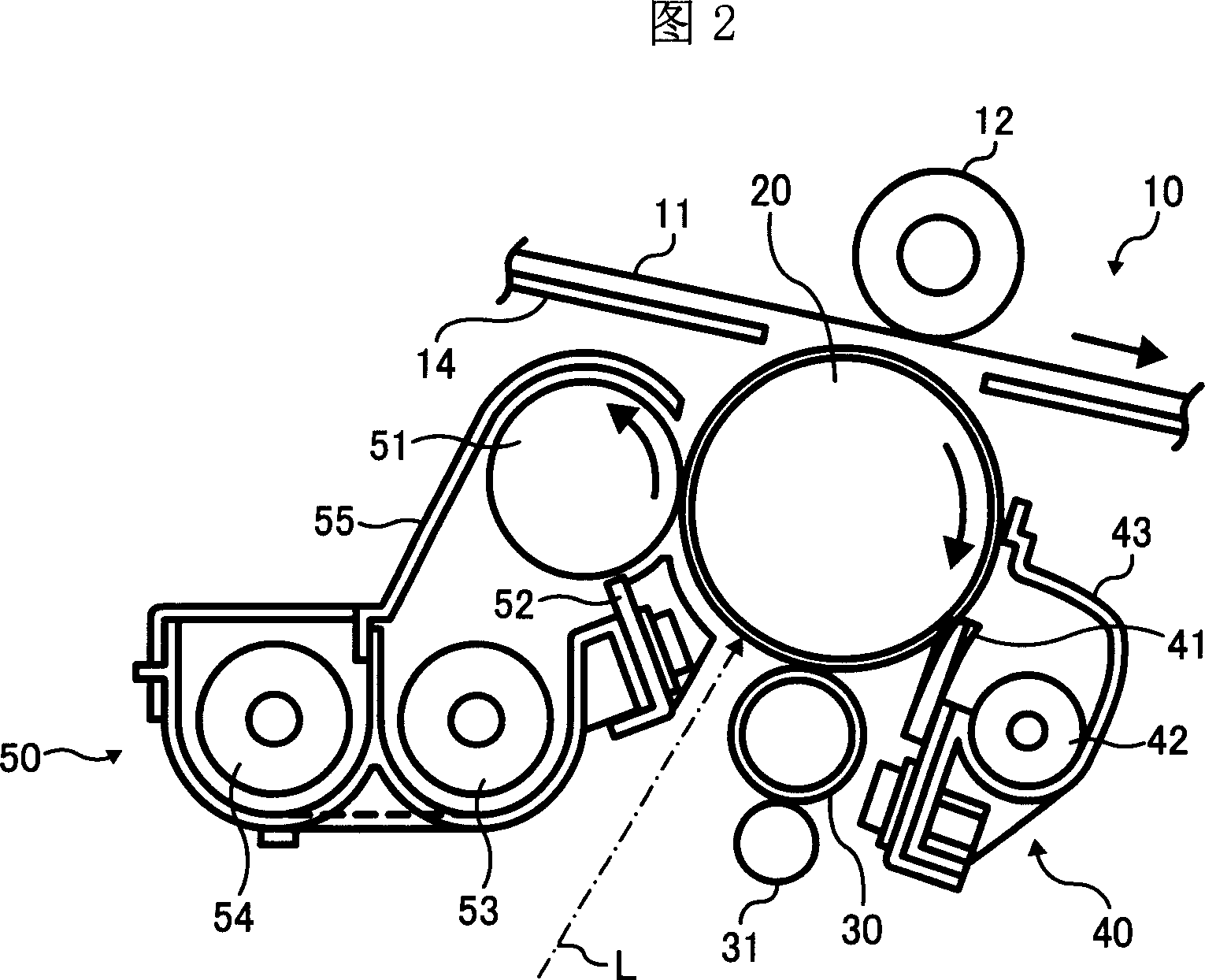
Image forming apparatus
An image and fixing part technology, which is applied in the direction of electric recording process applying charge pattern, equipment of electric recording process applying charge pattern, electric recording technique, etc., can solve the problem of increasing the adjustment range of the speed of the fixing part and the positioning part that is not recorded. methods, etc.
- Summary
- Abstract
- Description
- Claims
- Application Information
AI Technical Summary
Problems solved by technology
Method used
Image


Examples
Embodiment 1
[0059] FIG. 4 shows a paper transport path of Embodiment 1 of the image forming apparatus according to the present invention. The transfer material 4h is supplied from a cassette (not shown) located at the bottom of the drawing, and the timing of conveying the paper to the pair of registration rollers 4i is controlled so as to match the conveyance of the pre-transfer image. The transfer is carried out at the nip between the transfer roller 4j (transfer belt 4k) and the transfer roller 5, and the transferred transfer material 4h is conveyed in its original state, and is transferred by the fixing roller 4b (fixing belt 4m) and the pressure roller. The nip formed in 4a receives pressure and heat to fix the image. In FIG. 4, the front end 4c of the transfer material 4h is at the position of the fixing nip, and the transfer material 4h is curved due to the angle of the transport path and the rigidity of the paper.
[0060] Generally, the transfer material passes along the above-me...
Embodiment 2
[0076] In the image forming apparatus according to the present invention, when double-sided paper feeding is performed, the transfer material 4h printed on the first side is turned toward the paper discharge direction, and then passes through the double-sided conveying path and enters the positioning unit again. At this time, since the transfer material 4h receives heat in the fixing section, the diameter of the registration roller 4i thermally expands when double-sided continuous paper feeding is performed, and the paper conveyance speed in the positioning section gradually increases. In this way, since the transfer material 4h is pushed by the positioning part and slides on the transfer part, the image is blurred.
[0077] Therefore, in this embodiment, in the case of double-sided paper passing, the diameter and conveying speed of the positioning roller after expansion are calculated according to the number of sheets or the time of continuous paper passing according to experi...
Embodiment 3
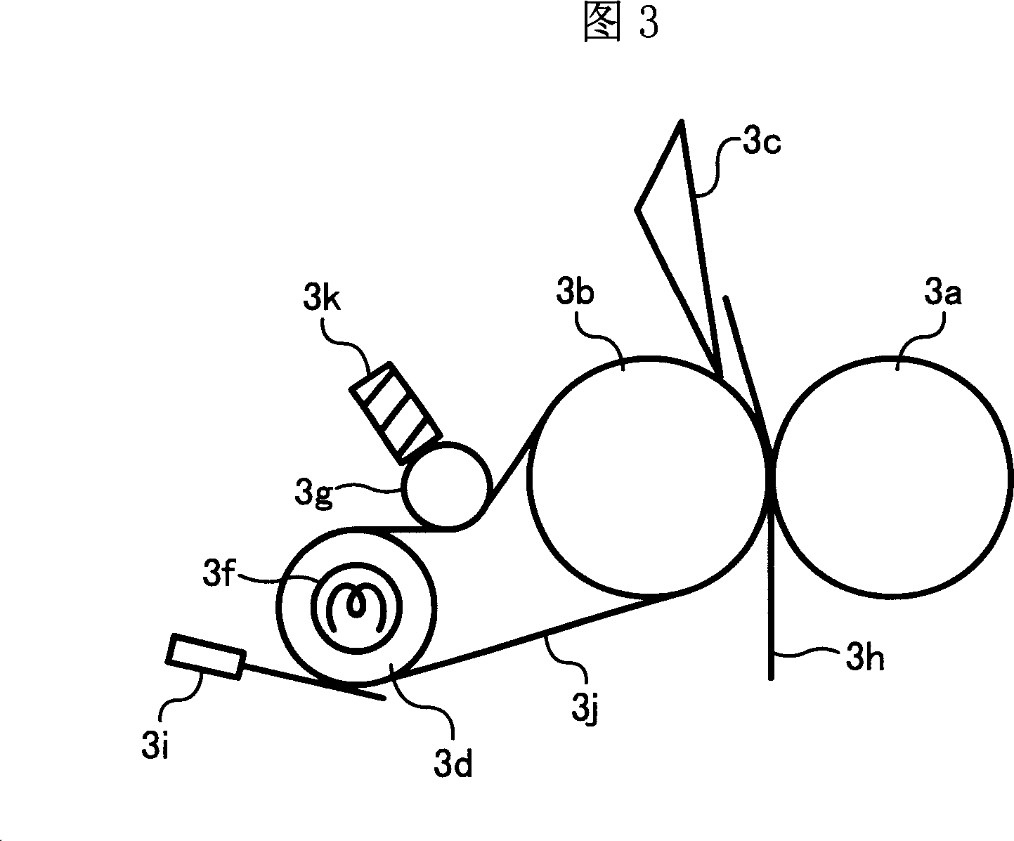
[0079] In this embodiment, as shown in FIG. 6A, when the paper is pressed by a predetermined force between the fixing unit and the transfer unit, a retractable guide member is provided. The guide member 6e is rotatably supported by a hinge portion 6f, and is energized by a spring 6d or the like with a predetermined load to guide ribs made of resin or guide surfaces made of metal plates. It is also possible to bond polyester resin (mylar) into a curved shape so as to have appropriate elasticity in the curved portion. In the case of the conveyance path as described above, even if the transfer material 6h is pushed and bent to Lmax, as shown in FIG. paper delivery channel.
[0080] In addition, by the above-mentioned guide, by satisfying the following formulas:
[0081] Vtc>(Lp-Lmax) / Tr and
[0082] Vth<(Lp-Lmin) / Tr
[0083] Can not be affected by the fixing state, avoid shock vibration and friction image.
[0084] The transfer unit may be configured as a transfer belt. In ...
PUM
 Abstract
Description
Claims
Application Information
 - R&D
- Intellectual Property
- Life Sciences
- Materials
- Tech Scout
- Unparalleled Data Quality
- Higher Quality Content
- 60% Fewer Hallucinations
Browse by: Latest US Patents, China's latest patents, Technical Efficacy Thesaurus, Application Domain, Technology Topic, Popular Technical Reports.
© 2025 PatSnap. All rights reserved.Legal|Privacy policy|Modern Slavery Act Transparency Statement|Sitemap|About US| Contact US: help@patsnap.com