
Magnet sensor arrangement

A technology of magnetic sensors and sensor elements, applied in the direction of converting sensor output, measuring devices, and adopting electrical devices, etc., which can solve problems such as eliminating deviations

Inactive Publication Date: 2007-03-14
ROBERT BOSCH GMBH
View PDF1 Cites 17 Cited by
  • Summary
  • Abstract
  • Description
  • Claims
  • Application Information

AI Technical Summary

Problems solved by technology

However, the compensation of the magnets used so far can no longer be carried out here, so that the offset cannot be eliminated at the two positions of the sensor elements of the gradiometer device; electronic compensation is possible in principle, but here there is a limitation on large offsets. relatively small signal

Method used


Image

  • Magnet sensor arrangement
  • Magnet sensor arrangement
  • Magnet sensor arrangement

Examples


Embodiment Construction

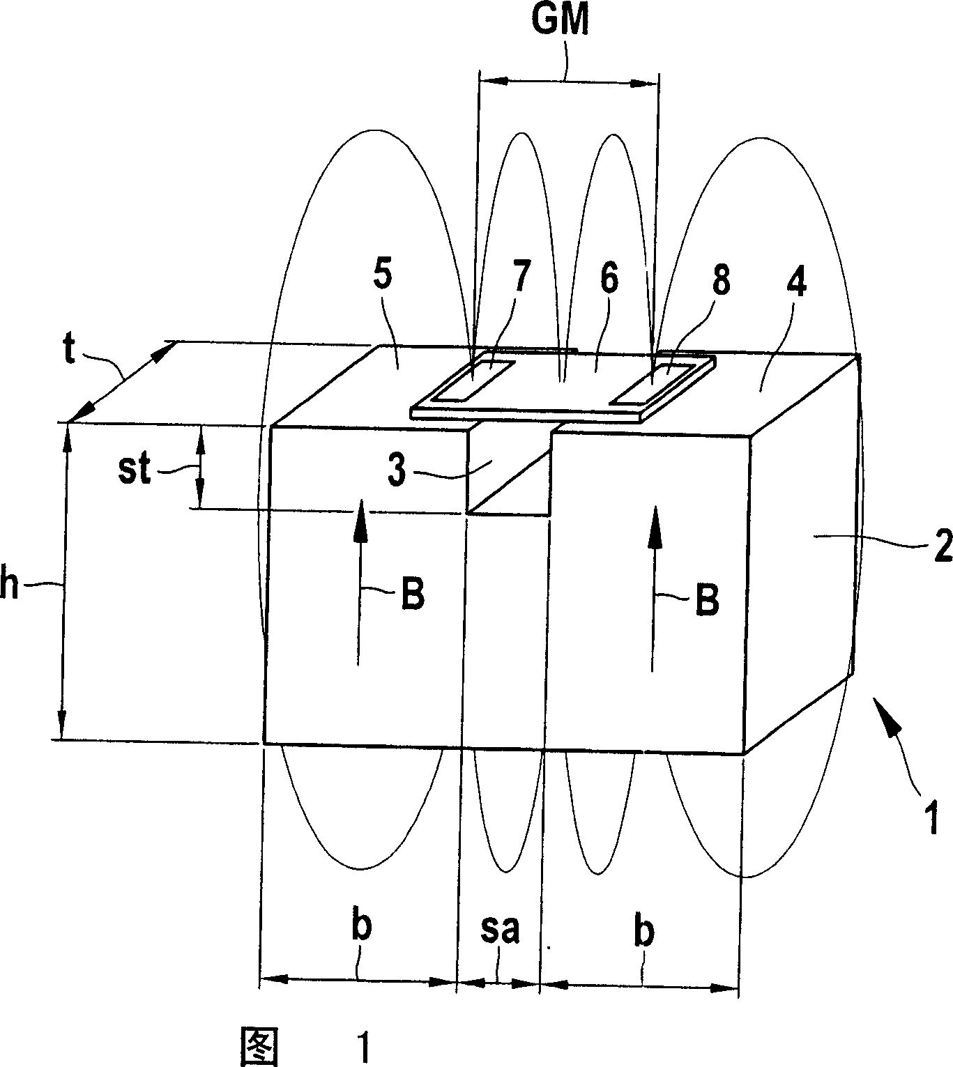
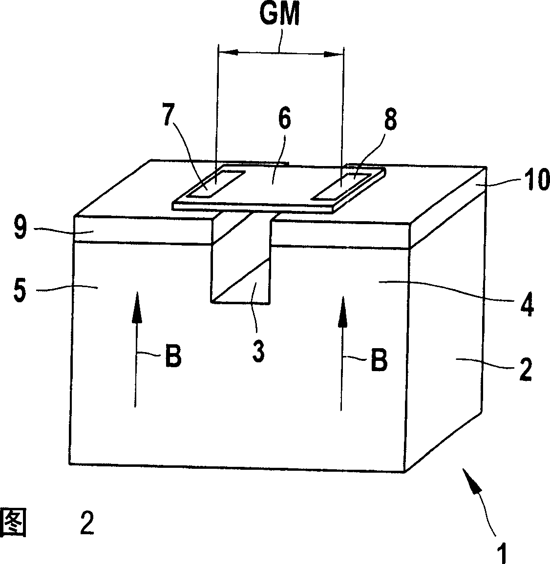
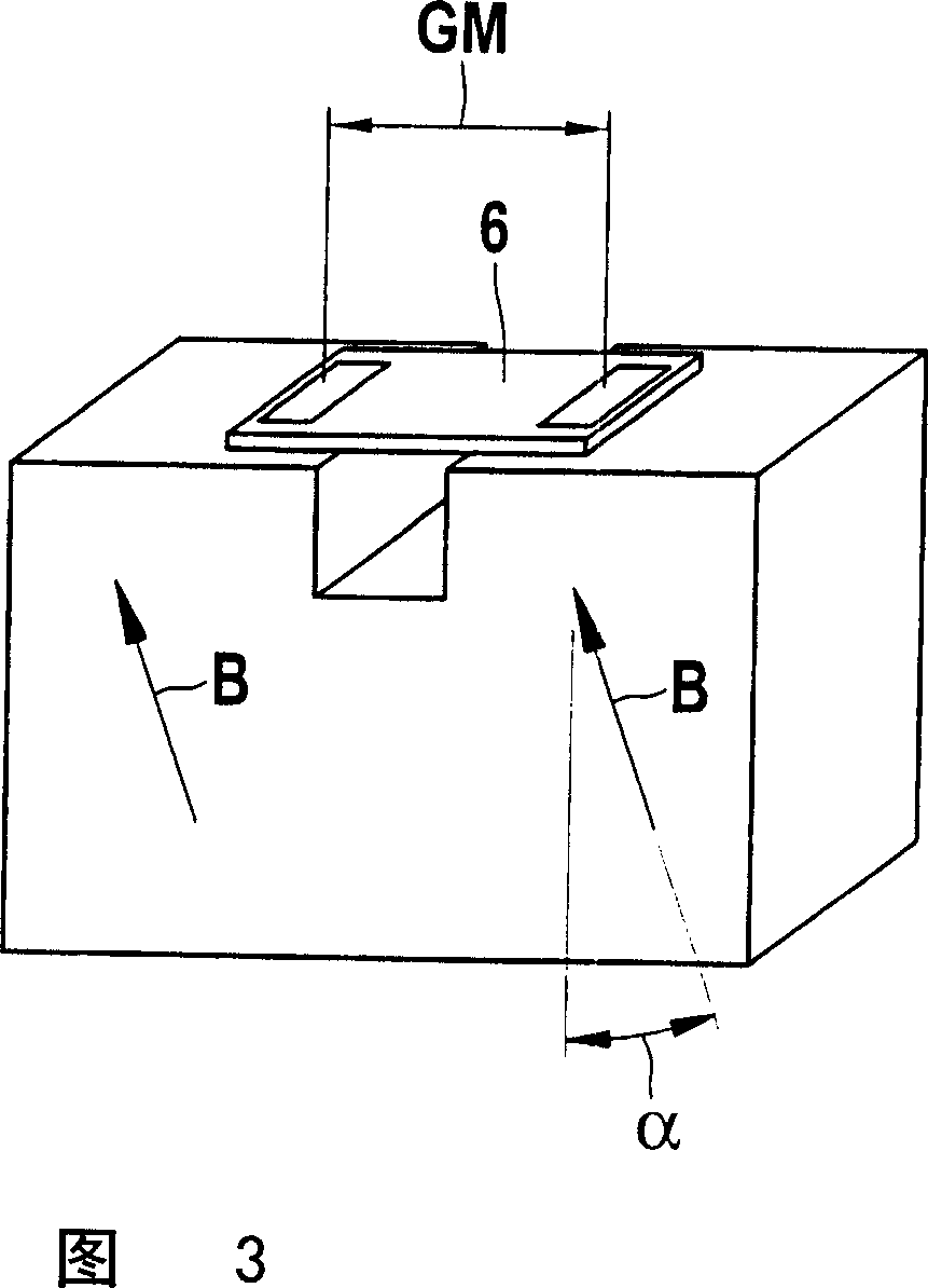
[0031] FIG. 1 shows a schematic illustration of a magnetic sensor device 1 with a permanent magnet embodied as a split magnet 2 . The open magnet 2 has regions 4 and 5 magnetized in the same direction on both sides of the opening 3 , whose corresponding magnetic field B with the field lines depicted here is aligned in the direction of the sensor 6 . The sensor 6 is here embodied as an XMR sensor and has two magnetoresistive sensor elements 7 and 8 . The sensor elements 7 and 8 are shown positioned in the gradiometer arrangement at a gradiometer interval GM and detect changes in the respective field gradients, for example by a metallic transmitter element guided past the magnetic sensor arrangement 1 , for example FIG. 5 caused by the gear shown in .

[0032] The setting of the optimum operating point of the sensor 6 is achieved by the mutual spacing of the individual magnets 4 and 5 defined by the opening width sa and the opening depth st and can be matched to the gradiometer...


PUM


Abstract

A magnetic sensor device (1) is proposed in which magnetic field-sensitive sensor elements (7, 8) are arranged, the electrical properties of which sensor elements (7, 8) can be changed as a function of a magnetic field which can be source transmitter element (11) to affect. The magnetic sensor device (1) has two sensor elements (7, 8) in the gradiometer device, which are assigned to permanent magnets (2; 20; 23) in each case One of two magnetic regions ( 4 , 5 ) of the magnet that are arranged at a predetermined distance (sa). Areas (4, 5) and opening magnets (2; 20; 23) in terms of eg wedge shape, dimensions (h, b, t), opening width (sa) and opening depth (st) and their relative to the sensor element ( 7 , 8 ) are positioned in such a way that deviations of the output signals of the sensor elements ( 7 , 8 ) are minimized in the gradiometer arrangement.

Description

technical field [0001] The invention relates to a magnetic sensor device, in particular for detecting the movement of a linearly or rotationally moving element, according to the features of the preamble of the main claim. Background technique [0002] It is known per se that sensors sensitive to magnetic fields are used in many fields in which it is desired to detect movements without contact. In this case, both rotary and linear movements can be involved. A distinction should be made here between two fundamentally different measurement principles. On the one hand, by arranging one or more magnetic dipoles as active elements on the element to be detected, the motion can be determined directly via the time-varying magnetic field at the sensor location. In contrast to this, in the case of a passive transmitter element made of soft magnetic material, the magnetic field is generated by a working magnet firmly connected to the sensor. The sensor measures changes in the magneti...

Claims


Application Information

Patent Timeline
IPC IPC(8): G01D5/16G01R33/022G01B7/02G01B7/30G01D5/14G01D5/244G01D5/245G01P3/488
CPCG01P3/488G01D5/147G01D5/24438G01D5/2451
Inventor R·雷蒂希C·鲍尔B·福格尔格桑
Owner ROBERT BOSCH GMBH
Learn More