
Chucking mechanism of dynamic clamp head capable of not damaging tube

A clamping mechanism and power tong technology, applied in the field of power tongs, can solve the problems of accelerating galvanic corrosion, affecting the service life of the pipe body, and damaging the pipe body.

Inactive Publication Date: 2007-03-14
付蕾
View PDF0 Cites 1 Cited by
  • Summary
  • Abstract
  • Description
  • Claims
  • Application Information

AI Technical Summary

Problems solved by technology

The puncture of the pipe body not only directly damages the pipe body, but also the internal stress caused by the scar will accelerate the galvanic corrosion and affect the service life of the pipe body

Method used

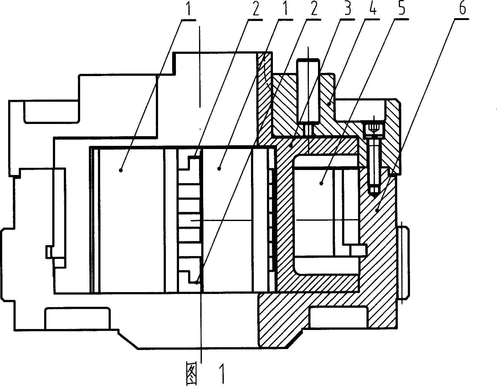
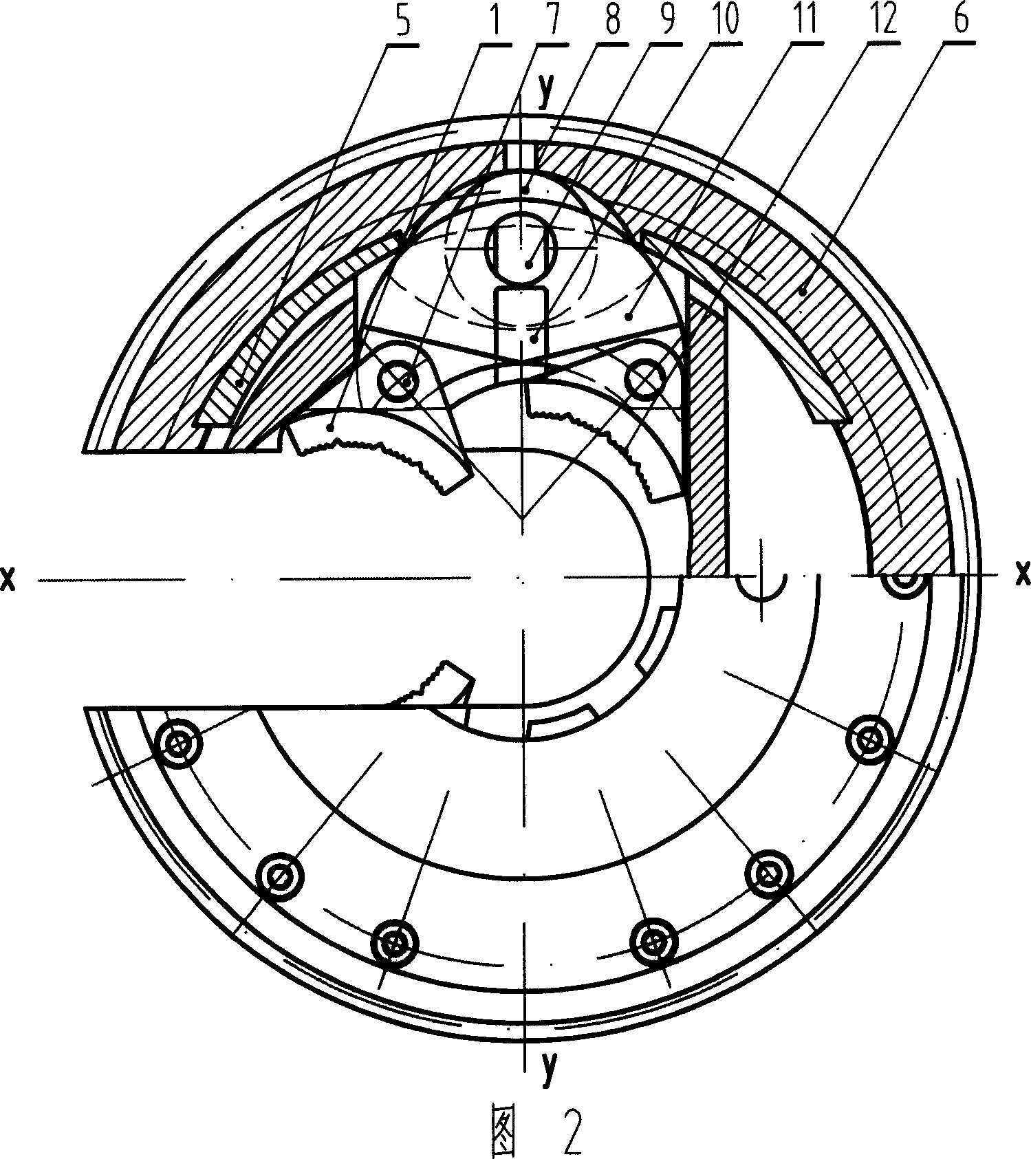
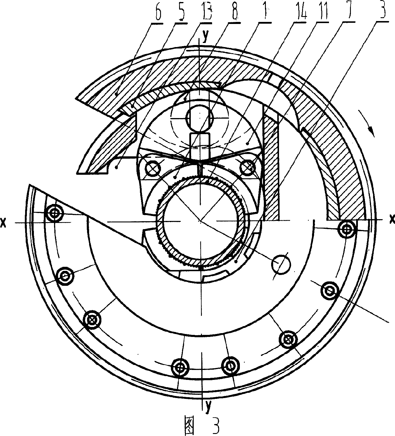

Image

  • Chucking mechanism of dynamic clamp head capable of not damaging tube
  • Chucking mechanism of dynamic clamp head capable of not damaging tube
  • Chucking mechanism of dynamic clamp head capable of not damaging tube

Examples


Embodiment Construction

[0012] As shown in Figures 1 and 2, the technical solution of the present invention is: a clamping mechanism of a power pliers head that does not damage the pipe body. , jaw plate 11, jaw plate roller 8, roller shaft 9, inner curved tooth plate 1, tooth plate rotating shaft 7, the inner side of the open gear 6 has an axial dovetail groove, the inner curved slope plate 5 is embedded in it, and the jaw plate frame 3 Located inside the open gear 6, there are square holes for installing the jaw plate 11 on both sides of the symmetrical opening. There are guide grooves 2 on the upper and lower sides of the square hole on the y-coordinate axis. The protruding guide rail 10 can slide radially and centripetally along the upper and lower guide grooves 2 of the jaw plate frame 3. There is a shaft hole on its symmetrical center line, and the roller shaft 9 is installed in it. The roller 8 is located between the two shaft holes and can surround The roller shaft 9 rotates, and the two ends...


PUM


Abstract

The invention relates to a power clamper compressor without hurting tube. Wherein, it comprises open wheel, open wheel cover, chop support, inner slope plate, arc chop, chop roller, roller axle, inner bend tooth plate and tooth plate rotation axle; the inner slope plate is embedded into the dovetail groove of open wheel; two chops have guide wheels to slide along the guide groove of chop support; the chops are symmetry; two inner bend tooth plates via tooth plate rotation axle are hinged to the chops; the inner curvature of inner bend tooth plate has axial bald tooth; four inner bend tooth plates contains 340degree of the surface of clamped tube; when one chop moves to another, the inner bend tooth plate can be replaced easily. The invention can clamp the tube reliability and prolong the service life.

Description

technical field [0001] The invention relates to a power tong for loading and unloading pipe string threads, in particular to a clamping mechanism of a power tong head which does not damage the pipe body. Background technique [0002] In the existing power tongs for loading and unloading pipe string threads, the clamping mechanism of the tong head is usually provided with an inner curved ramp plate inside the open gear, the jaw plate frame is contained in the inner cavity of the open gear, and there is a jaw plate assembly in the jaw plate frame. The plate frame is temporarily braked, and when the open gear rotates relative to the jaw plate frame, the rollers in the two jaw plate assemblies roll and climb along the slope, so that the jaw plate frame assembly moves centripetally, and the jaw plate assembly in the jaw plate assembly The tooth block rotates together after contacting the clamped pipe body to implement the make-up or breakout of the pipe thread. There are usually ...

Claims


Application Information

Patent Timeline
IPC IPC(8): B25B21/00B25B23/00
Inventor 付蕾
Owner 付蕾
Learn More