Eureka AIR delivers breakthrough ideas for toughest innovation challenges, trusted by R&D personnel around the world.

Large axle load bogie

A bogie and large axle load technology, which is applied in the direction of the device for lateral relative movement between the underframe and the bogie, to achieve the effects of reduced wheel-rail force, high structural strength, and improved curve passing performance.

Active Publication Date: 2007-02-28
CRRC MEISHAN
View PDF0 Cites 5 Cited by
  • Summary
  • Abstract
  • Description
  • Claims
  • Application Information

AI Technical Summary

Problems solved by technology

This kind of bogie has achieved certain effects in smooth operation and reducing wheel-rail wear, but due to design defects, the above-mentioned problems have not been fundamentally resolved, and other wear and maintenance problems have arisen

Method used


Image

  • Large axle load bogie
  • Large axle load bogie
  • Large axle load bogie

Examples


Embodiment Construction

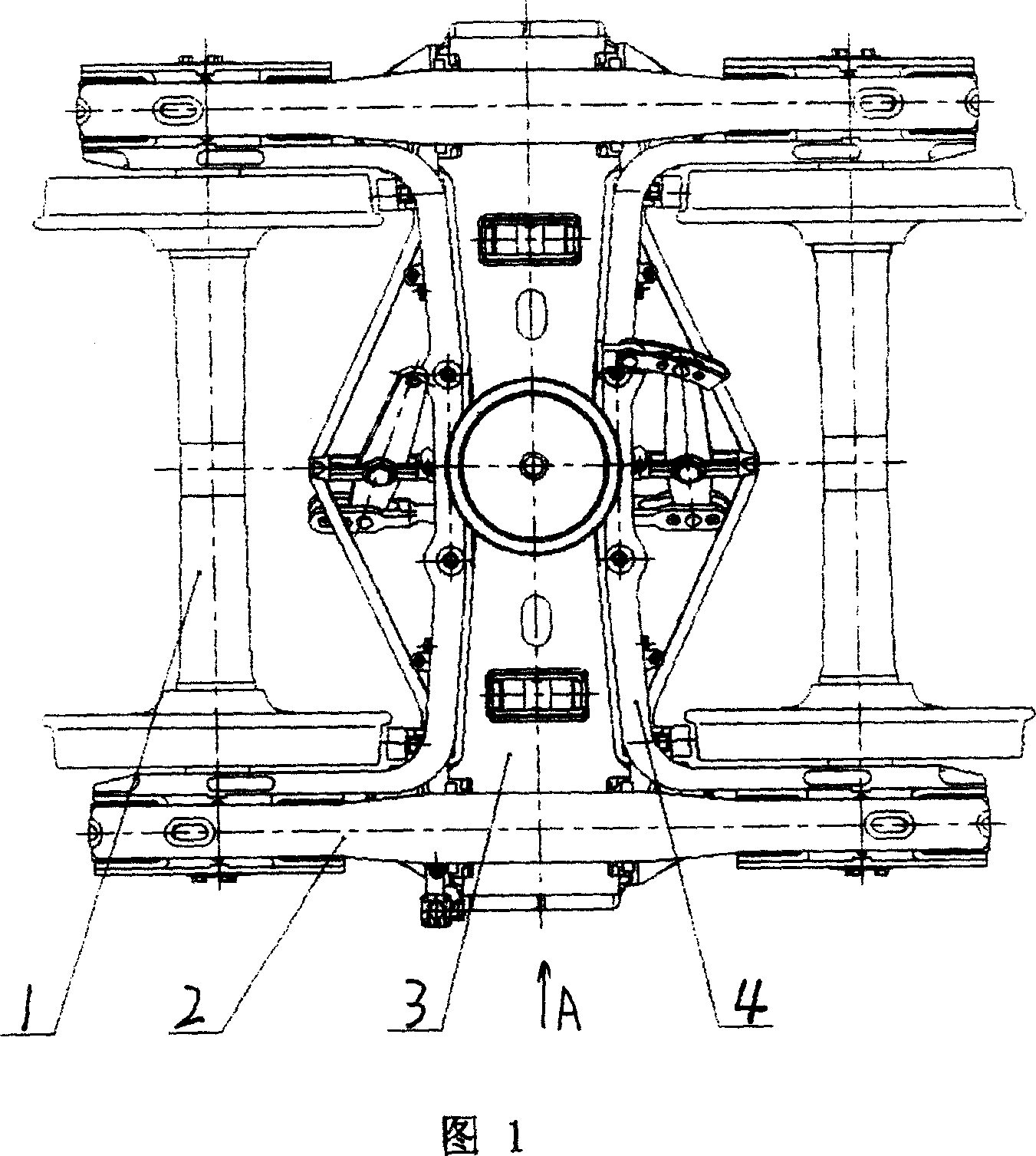
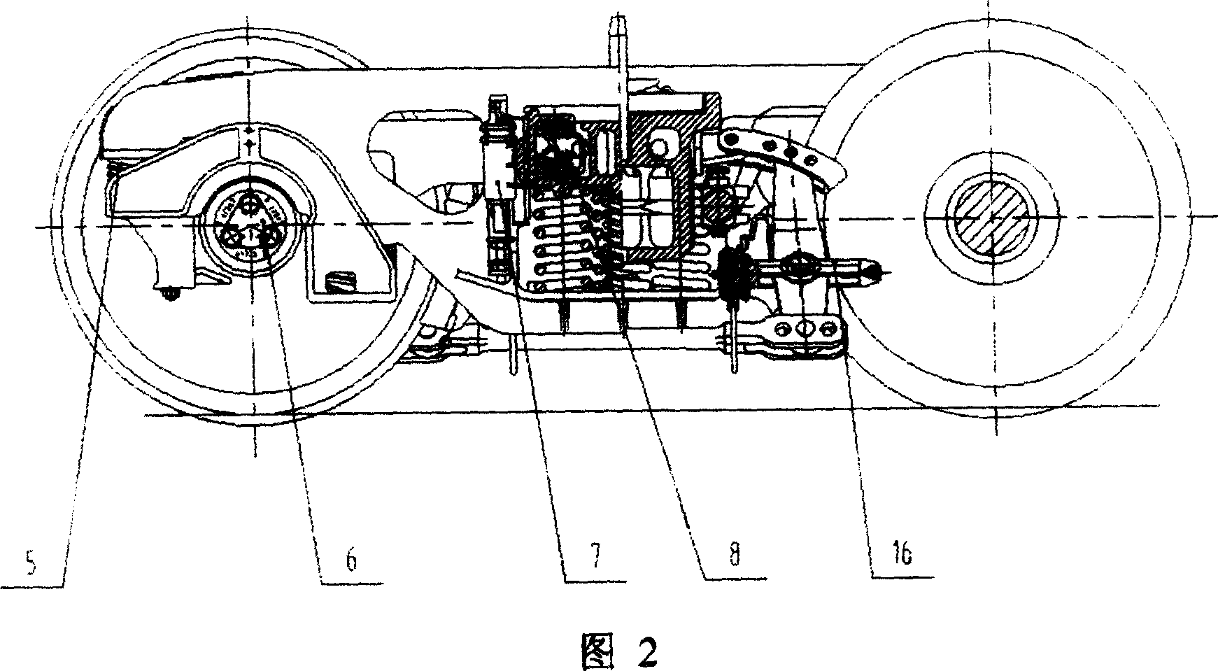
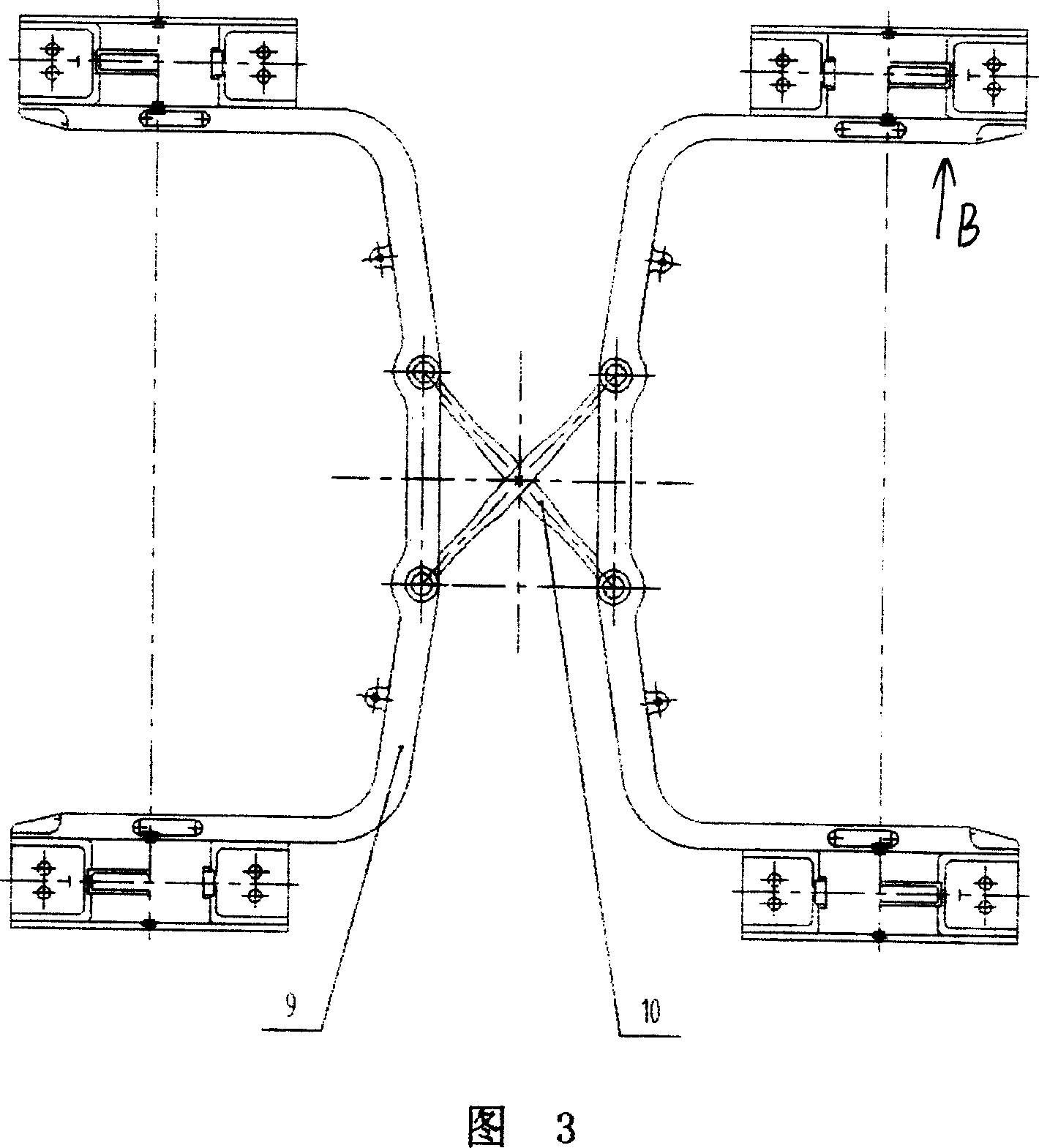
[0022] Referring to the accompanying drawings, the present invention includes a wheel set 1, a side frame 2 and a bolster 3. The wheel set 1 is formed by connecting left and right wheels through an axle, and two adjacent sets of wheels are respectively located on both sides of the bolster 3, forming bogie. The key technology is to install the sub-frame 9 on the bearings 6 at both ends of the axle of the wheel set 1, that is, the two ends of the sub-frame 9 are respectively installed on the bearings 6 at both ends of the axle, and the sub-frame 9 is formed by a tie rod passing through the middle of the bolster 3 10 are connected by pin joints, the sub-frame 9 and the tie rod 10 connected to it form the self-guiding device 4 of the bogie, and the inner sides of both ends of the sub-frame 9 adopt a U-shaped box structure as shown in Figure 4 . The two ends of the sub-frame 9 are fitted with side frames 2, and an elastic device 5 is installed between the side frame 2 and the sub-f...


PUM


Abstract

The invention discloses a steel three-part control pattern structure steering rack with self-guide device, which loads self-guide device on the traditional three-part steel steering rack with elastic device between self-guide device and lateral rack.

Description

(1) Technical field: [0001] The utility model relates to a bogie with a large axle load, which relates to a railway cargo transportation device, in particular to a bogie used for railway wagons for international intermodal transportation. (two) background technology: [0002] In terms of heavy-duty transportation, increasing the weight of a single vehicle is one of the important ways to improve transportation efficiency. According to foreign experience, increasing the vehicle axle load is an inevitable trend. About 65% of the trucks on American railways use F axles (axle load 29.18t), and some use G axles (axle load 35.17t); the axle load of Australia's BHP heavy-duty line has been increased to 35t; The weight has reached 30t; the axle load of the South African heavy-haul railway has reached 26t (narrow gauge); the Swedish heavy-haul railway has increased the axle load from 25t to 30t; Russia has generally adopted 23.15t axle load, and is stepping up research to apply to 35...

Claims


Application Information

Patent Timeline
Patent Type & Authority Applications(China)
IPC IPC(8): B61F5/02
Inventor 尹买云潘树平肖乾佑肖颖瘳军
Owner CRRC MEISHAN
Why Eureka
Eureka Blog
Learn More