
Combustion device

A combustion device and fuel technology, applied in burners, combustion chambers, combustion methods, etc., can solve the problems of low total air ratio and difficult combustion, and achieve the effect of high stability

Inactive Publication Date: 2007-02-21
EBARA CORP
View PDF5 Cites 8 Cited by
  • Summary
  • Abstract
  • Description
  • Claims
  • Application Information

AI Technical Summary

Problems solved by technology

In conventional gas turbine combustors, the target temperature is considerably lower than the flame temperature during combustion with a theoretical air volume that just contains the amount of oxygen required for fuel combustion, so the total air ratio is extremely low. Low, it is difficult to burn at level 1 when using normal hydrocarbon-based fuels

Method used


Image

  • Combustion device
  • Combustion device
  • Combustion device

Examples


Embodiment Construction

[0103] Below, refer to Figure 5 to Figure 38 , the combustion device according to the embodiment of the present invention will be described. In addition, in each embodiment, the same code|symbol is attached|subjected to the same part, and overlapping description is abbreviate|omitted.

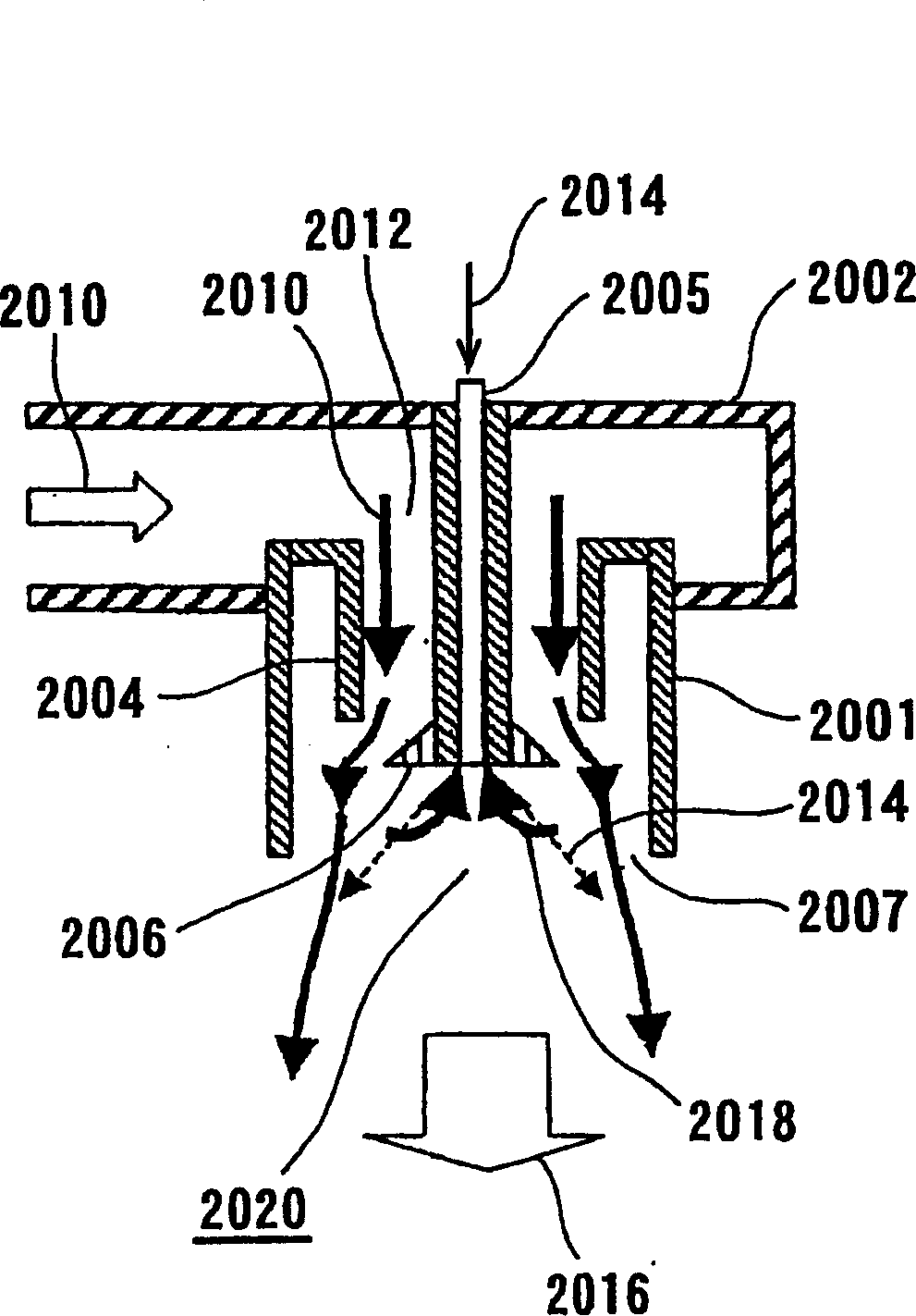
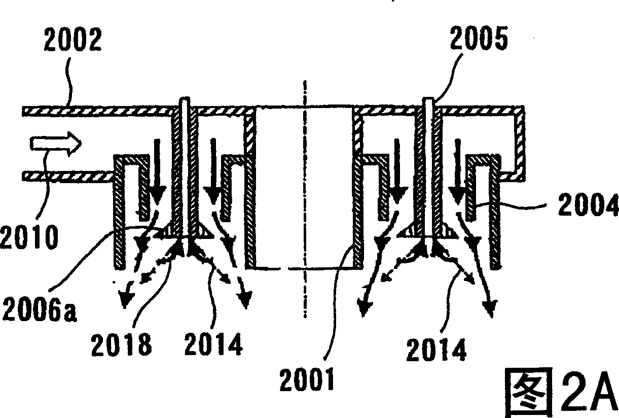
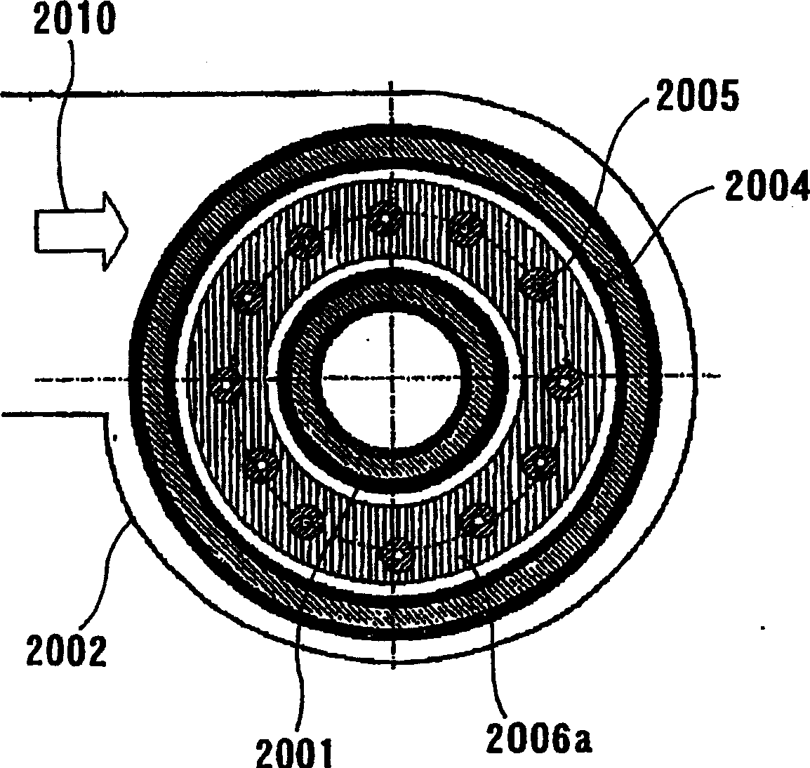
[0104] First, refer to Figure 5 and Figure 6, the combustion device in the first embodiment will be described. Figure 5 The combustion device shown has an annular vessel 12 closed at one end (closed end) 10, an inflow housing 14, a gyrator 16 and fuel disposed on the inside at the upper end (closed end) 10 of said annular vessel 12 Nozzle 18. On the side surface of the outer periphery of the annular container 12 (outer cylinder portion 13 described later), a plurality of air inflow portions 20 are formed at the same pitch, so that combustion air 22 flows into the annular container 12 through the air inflow portions 20 . The inflow path formed by the air inflow part 20 , the inflow hous...


PUM


Abstract

A combustion apparatus capable of producing the recirculation of combustion gas by positively controlling the recirculation by a simple structure. The combustion apparatus comprises an annular container (12) having an inner tube part (15) forming an inner peripheral side face, an outer tube part (13) forming an outer peripheral side face, an open end part (26), and a closed end part (10). An air flow (28) having a speed component in the direction of a center axis (J) starting at the open end part (26) toward the closed end part (10) and a speed component in the circumferential direction of the annular container (12) is formed in the apparatus. A fuel (23) is jetted to have a speed composition in the direction of the center axis (J) starting at the closed end part (10) toward the open end part (26) and a speed component in the radial outer direction.

Description

technical field [0001] The present invention relates to a combustion device, and more particularly, to a combustion device that flows combustion air and fuel into a combustion chamber, mixes the combustion air and fuel, and performs combustion. Background technique [0002] Regulations on air pollutants discharged from combustion devices, especially nitrogen oxides (NOx) have been increasingly tightened, and reductions in NOx emissions have been sought. [0003] Nitrogen oxides (NOx) are roughly classified into three types, thermal NOx, prompt NOx, and combustion NOx, according to their generation mechanism. Thermal NOx is strongly dependent on temperature because it is produced by the reaction of nitrogen and oxygen in the air at high temperature. Prompt NOx is formed especially in fuel-rich flame belts. Combustion NOx is generated in association with nitrogen compounds contained in fuel. [0004] Recently, clean fuels that do not contain nitrogen compounds are frequentl...

Claims


Application Information

Patent Timeline
Patent Type & Authority Applications(China)
IPC IPC(8): F23D11/12F23D14/02F23D21/00F23C3/00F23C7/02F23C9/00F23D99/00F23R3/06F23R3/46
CPCF23C7/02F23C9/006F23R3/46F23R3/06F23C3/006F23R3/50
Inventor 天野俊辅新井雅隆
Owner EBARA CORP
Learn More