
Plasma display device

A display device and plasma technology, applied in identification devices, static indicators, instruments, etc., can solve problems affecting stable discharge, achieve stable discharge characteristics, improve efficiency, and save costs

Inactive Publication Date: 2007-02-21
LG ELECTRONICS(NANJING) PLASMA CO LTD
View PDF0 Cites 0 Cited by
  • Summary
  • Abstract
  • Description
  • Claims
  • Application Information

AI Technical Summary

Problems solved by technology

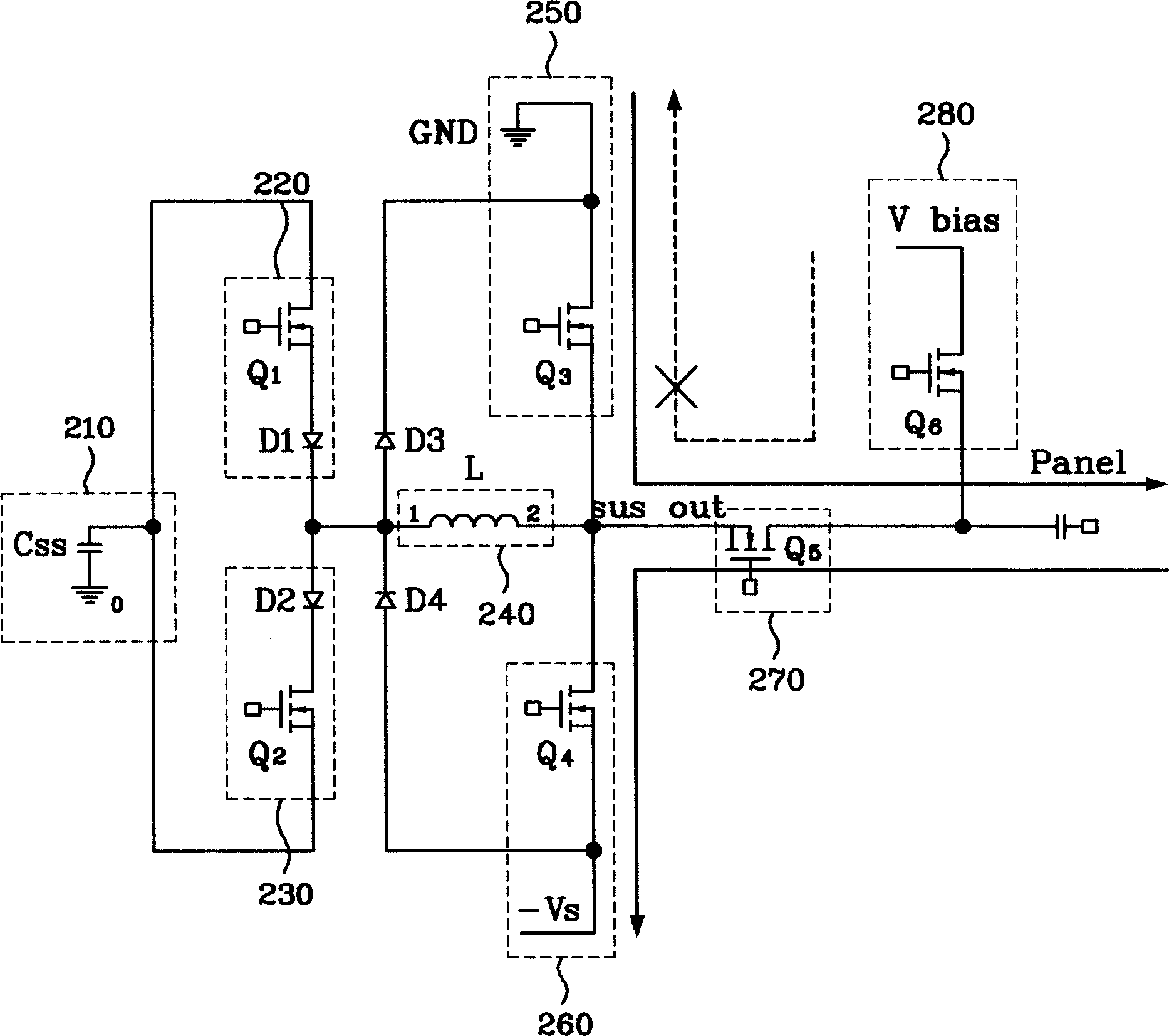
Also, due to this withstand voltage characteristic, the impedance (impedance) of the switching element will affect the characteristics of obtaining stable discharge

Method used


Image

  • Plasma display device
  • Plasma display device
  • Plasma display device

Examples


Embodiment Construction

[0030] Hereinafter, the plasma display device in the present invention will be described in detail with reference to preferred embodiments and accompanying drawings.

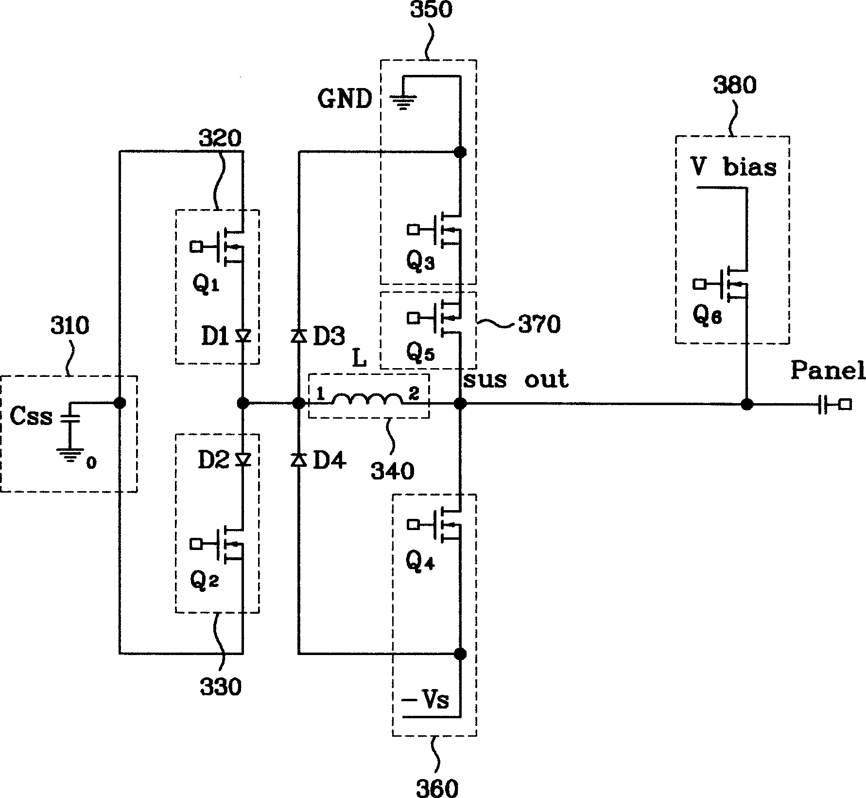
[0031] image 3 It is a schematic diagram of the cathode (negative) sustain driving circuit of the sustain electrode in the present invention.

[0032] refer to image 3 , in one embodiment of the present invention, the driving device of the plasma display panel includes: an energy recovery circuit that supplies energy to the panel (Cp) and recovers it; a bias supply unit 380 that supplies a bias voltage to the sustain electrode during positioning; The base voltage supply part 350 which supplies the base voltage to the sustain electrode during the sustain period; the sustain voltage supply part 360 which supplies the sustain voltage to the sustain electrode during the sustain period; The short circuit prevention part 370 of the common end of the part 380 and the sustain voltage supply part 360 .

[0033] Fi...


PUM


Abstract

The present invention discloses a plasma display device comprising a plasma display panel containing maintaining electrode; a bias supplying part which supplies bias to the maintaining electrode during positioning time; a base voltage supplying part which supplies base voltage to the maintaining electrode during maintaining time; a maintaining voltage supplying part which supplies maintaining voltage to the maintaining electrode during maintaining time; and a short circuit preventing part, one end of which is connected to one end of the base voltage supplying part, while the other end of which is connected to common end of the bias supplying part and the maintaining voltage supplying part. The present invention is capable of reducing the cost of the negative maintaining electrode drive circuit, and reducing the external loaded maintaining discharge voltage because the device of the present invention has low impedance and the voltages at both ends of the panel are higher than that before; and the present invention has stable discharge characteristics and is capable of improving the efficiency of the drive circuit and reducing the cost of the switching member of the short circuit preventing part.

Description

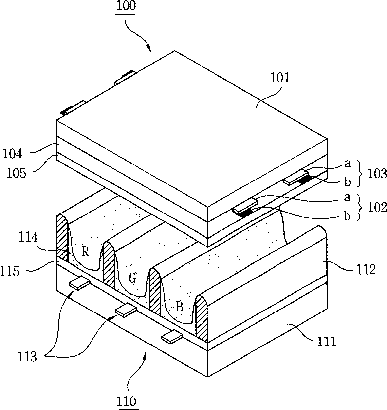
1. Technical field [0001] The invention relates to a plasma display device {Plasma Display panel Apparatus}. 2. Background technology [0002] A general plasma display panel consists of an interlayer formed between the upper substrate and the lower substrate to form a unit cell (cell), and each cell (cell) is filled with neon (Ne), helium (He), or a combination of neon and helium. Main discharge gas such as mixed gas (Ne+He) and a small amount of inert gas containing xenon. When the high-frequency voltage causes discharge, the inert gas generates vacuum ultraviolet rays (Vacuum Ultraviolet ray), which makes the phosphors formed between the interlayers emit light and display images. Such a plasma display panel has a light and thin structure, and is attracting attention as a next-generation display device. [0003] figure 1 It is a schematic structural diagram of a plasma display panel in the prior art. [0004] refer to figure 1 , a plasma display panel, a front panel 10...

Claims


Application Information

Patent Timeline
Patent Type & Authority Applications(China)
IPC IPC(8): G09F9/313H01J17/49G09G3/28G09G3/296G09G3/293G09G3/294
CPCG09G3/293G09G3/294G09G3/296
Inventor 白東基金泰忠
Owner LG ELECTRONICS(NANJING) PLASMA CO LTD
Learn More