Rotary electric machine
A technology of rotating motors and rotating shafts, which is applied in the direction of motors, electromechanical devices, electric vehicles, etc., can solve the problems of difficult output characteristics and heavy weight of rotating motors, and achieve the effect of accurate output characteristics and accurate control
- Summary
- Abstract
- Description
- Claims
- Application Information
AI Technical Summary
Problems solved by technology
Method used
Image

Examples
no. 1 approach
[0054] Next, a first embodiment of the present invention will be described with reference to the drawings.
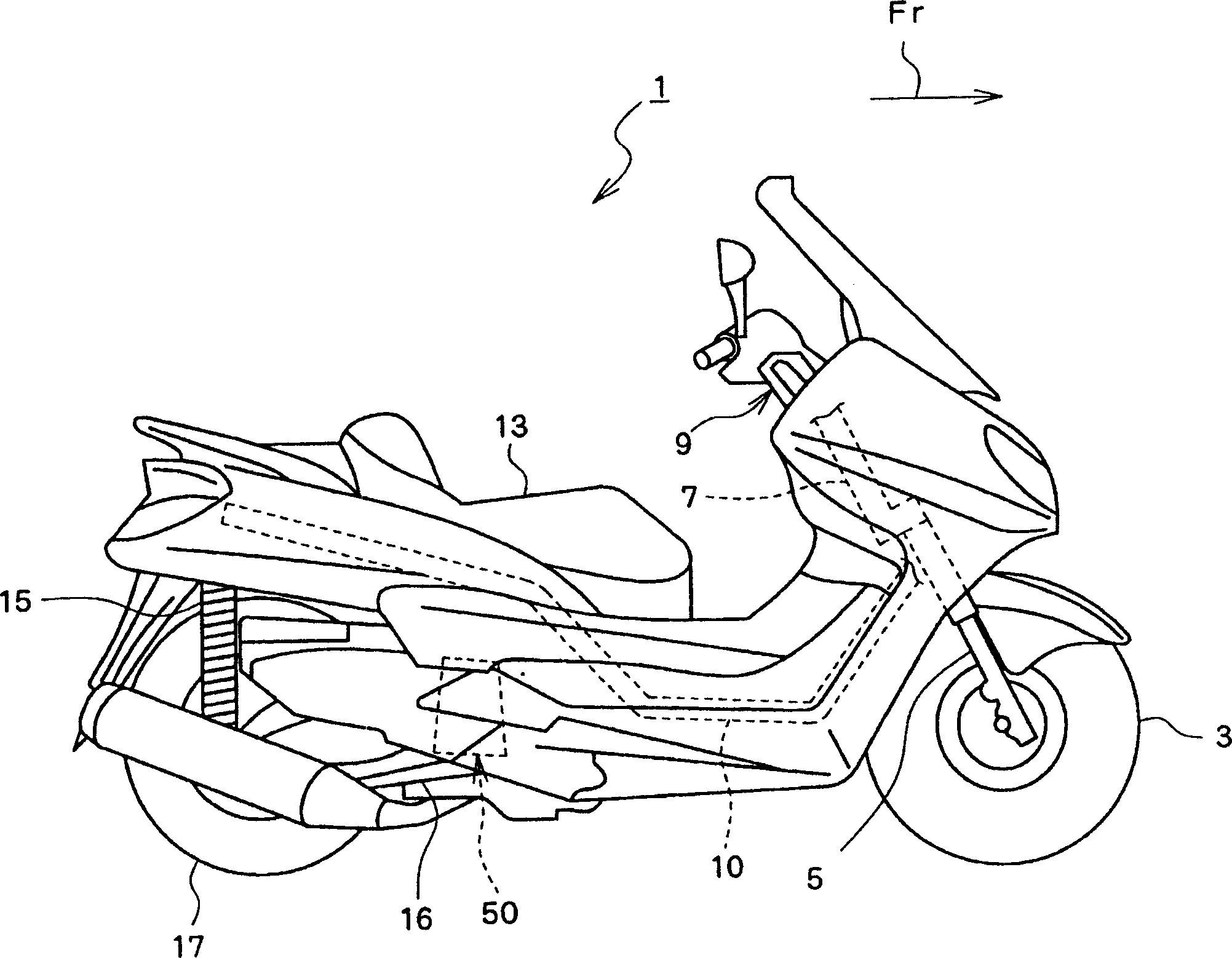
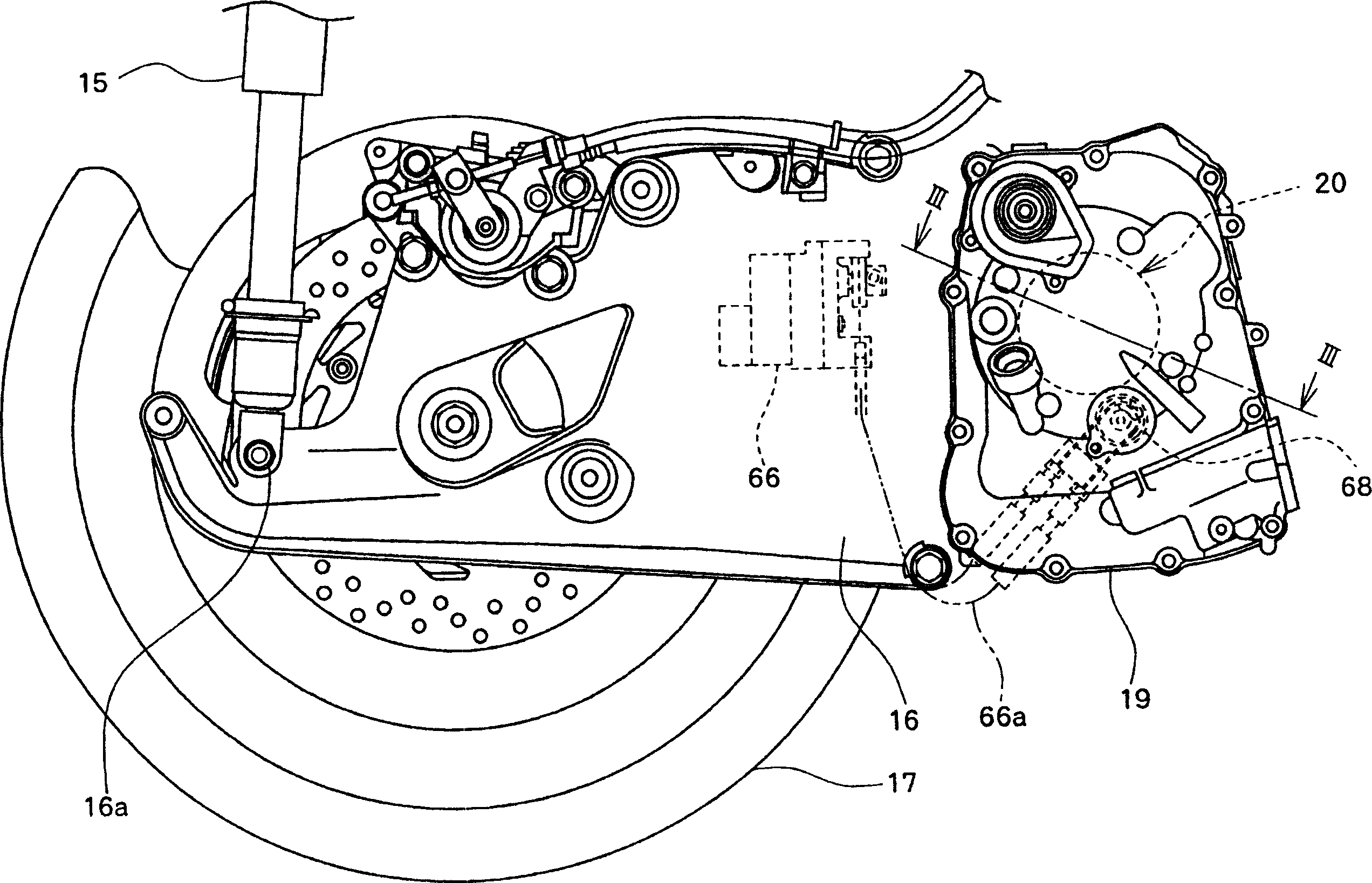
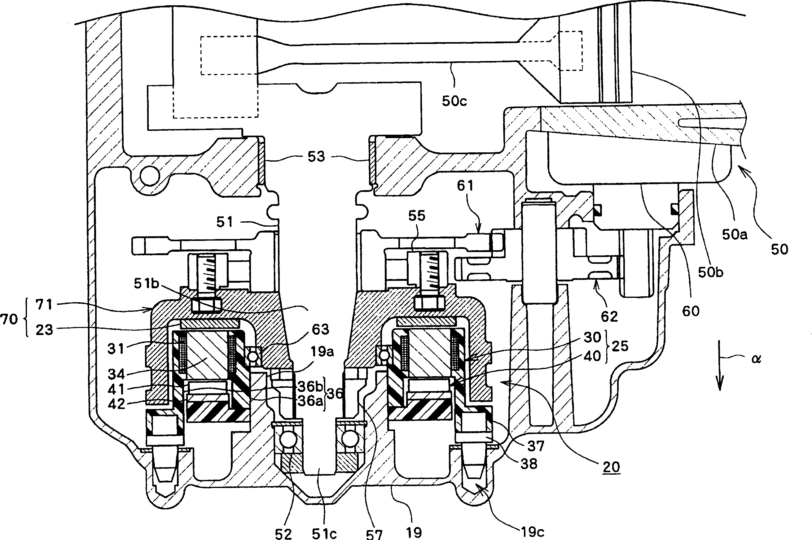
[0055] figure 1 is a side view of a motorcycle 1 equipped with a rotating electrical machine 20 having a stator 25 of the present invention, figure 2 is a side view of the rear of the motorcycle 1, image 3 is along figure 2 A cross-sectional view taken on line III-III, Figure 4 is has image 3 An enlarged view of the rotating electrical machine 20 with the stator 25 shown, Figure 5 is an exploded perspective view of the rotary electric machine 20 .
[0056] Such as figure 1 As shown, the motorcycle 1 has a front wheel 3 at the front lower part of the vehicle body, and the front wheel 3 is rotatably supported by the lower end of the front fork 5 . A steering shaft 7 extending upward is connected to an upper end portion of the front fork 5 . A handle 9 extending in the vehicle width direction is attached to an upper end portion of the steering shaft 7 . A bo...
no. 2 approach
[0108] Next, a second embodiment of the present invention will be described based on the drawings.
[0109] Figure 20 is a cross-sectional view of a rotating electrical machine 200 having a stator 250 according to a second embodiment of the present invention, Figure 21 is an exploded perspective view of the rotary electric machine 200 . Figure 22 yes Figure 20 magnified view of . In addition, in Figure 21 The crankshaft 51 is omitted. In addition, in Figure 20 The cylinder 50a etc. which are arrange|positioned at the center side of the crankshaft 51 are omitted in FIG. exist Figure 20 and Figure 21 In , the same reference numerals are assigned to the same parts as those of the stator 25 and the rotary electric machine 20 having the stator 25 described above, and description thereof will be omitted.
[0110] The rotating electrical machine 200 is a radial gap rotating electrical machine, that is, a rotating electrical machine in which a stator is disposed radia...
no. 3 approach
[0131] Next, a third embodiment of the present invention will be described based on the drawings.
[0132] Figure 26 is a cross-sectional view of a rotating electrical machine 220 having a stator 225 according to a third embodiment of the present invention, Figure 27 is an exploded perspective view of the rotary electric machine 220 . Figure 28 yes Figure 26 An enlarged view of the stator 225. In addition, in Figure 27 The crankshaft 51 is omitted in the Figure 26 The cylinder 50a etc. which are arrange|positioned at the center side of the crankshaft 51 are omitted in FIG. exist Figure 26 to Figure 28 In , the same reference numerals are assigned to the same parts as those of the rotary electric machine 200 described above, and description thereof will be omitted.
[0133] The rotating electrical machine 220 is substantially the same as the radial gap rotating electrical machine described above, and is characterized in that the stator 225 has a first stator 330 a...
PUM
 Abstract
Description
Claims
Application Information
 - R&D
- Intellectual Property
- Life Sciences
- Materials
- Tech Scout
- Unparalleled Data Quality
- Higher Quality Content
- 60% Fewer Hallucinations
Browse by: Latest US Patents, China's latest patents, Technical Efficacy Thesaurus, Application Domain, Technology Topic, Popular Technical Reports.
© 2025 PatSnap. All rights reserved.Legal|Privacy policy|Modern Slavery Act Transparency Statement|Sitemap|About US| Contact US: help@patsnap.com