Shaving head with skin stretching member

A skin, midsection technology applied in the field of shaving, which can solve the problem of stinging skin, shaved skin knife marks and wounds

Inactive Publication Date: 2011-07-13
KONINKLIJKE PHILIPS ELECTRONICS NV
View PDF2 Cites 0 Cited by
  • Summary
  • Abstract
  • Description
  • Claims
  • Application Information

AI Technical Summary

Problems solved by technology

But still there is such a problem in this known safety razor, that is, in the shaving operation, it is still possible to cause knife marks and wounds to the shaved skin, or to sting the skin

Method used


Image

  • Shaving head with skin stretching member
  • Shaving head with skin stretching member
  • Shaving head with skin stretching member

Examples


Embodiment Construction

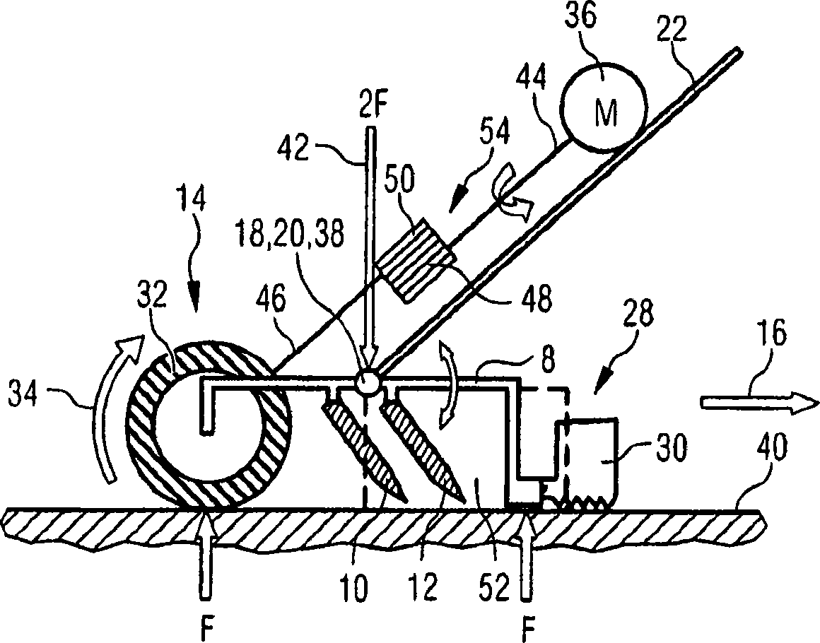
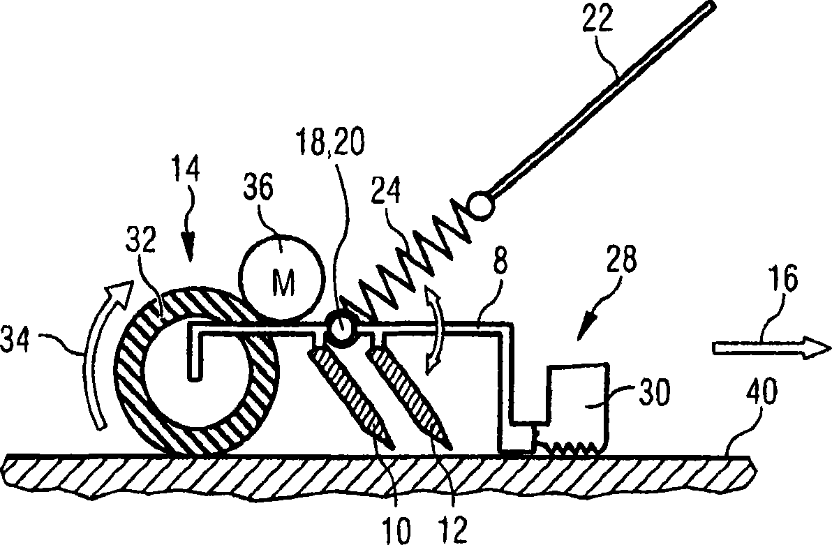
[0026] figure 1 is a simplified schematic diagram of the first embodiment of the shaving head 8 of the present invention. The shaving head 8 is coupled to the handle 22 by means of first coupling means 38 . The first coupling means 38 may for example take the form of one or more snap-in hooks on the shaving head 8 for snapping into one or more corresponding bridges on the handle 22 . The shaving head 8 comprises two blades 10 , 12 arranged to form a cutting direction 16 . Behind the blades 10, 12, relative to the cutting direction 16, a movably driven skin stretching device 14 is arranged. The movably driven skin stretching device 14 includes rollers 32 which can be driven by an electric motor 36 connected to the shaving head 8 . The roller 32 is driven such that the rotational direction 34 corresponds to the rotational winding direction 34 relative to the cutting direction 16 . In front of the blades 10, 12 with respect to the cutting direction 16, a guard 28 is arranged....


PUM


Abstract

The invention is directed to a shaving head (8) comprising at least one cutting blade (10, 12) and actively driveable skin stretching means (14) arranged behind said cutting blade (10, 12) relative to a cutting direction (16) of said cutting blade (10, 12). The actively driveable skin stretching means (14) are provided to reduce the possibility that ni cks and cuts or irritations of the skip to be shaved are created during the shaving operation. In accordance with the invention the shaving head (8) comprises means (18) for providing a pivot axis (20) between the shaving head (8) and a handie (22) attached or attachable to said shaving head (8), said pivot axis (20) being arranged at least essentially parallel to said cutting blade (10, 12). By providing the pivot axis (20) the force ratiobetween a force applied to the actively driveable skin stretching means (14) and forces applied to other parts ofthe shaving head (8) may be kept constant for different angles of the handle. This improves the functioning of the actively driveable skin stretching means (14).

Description

technical field [0001] The present invention relates to a shaving head, which comprises at least one blade, a movably driven skin stretching device arranged behind the blade relative to the cutting direction of the blade, and a guard device arranged at a position relative to the cutting direction of the blade. the front of the blade. Background technique [0002] Shaving heads of the type described above are well known in the art. This type of shaving is also known as a safety razor. But this known safety razor still has such a problem, that is, during the shaving operation, it is still possible to cause cuts and wounds to the shaved skin, or to sting the skin. [0003] This problem can at least be alleviated by providing skin stretching means behind the blades, eg in the form of driven rollers. Such a technical solution is known from DE19514228A1. This document discloses a razor with a shaving head of the type described above, in which a first roller is located in front...

Claims


Application Information

Patent Timeline
Patent Type & Authority Patents(China)
IPC IPC(8): B26B21/34B26B21/22
CPCB26B21/225B26B21/22B26B21/34B26B21/08
Inventor E·侯博尔特M·C·汉堡E·J·霍旭姆H·K·帕尤维M·维塞林H·阿克曼
Owner KONINKLIJKE PHILIPS ELECTRONICS NV
Why Eureka
Try Eureka