Vacuum Dispensing System

A dispensing and vacuum technology, which is applied to the device and coating of the surface coating liquid, can solve the problems of difficult use of electronic weighing equipment, pollution of the workbench, damage to parts, etc., and meet the requirements of reduction and extension Service life, impact prevention effect

Active Publication Date: 2022-07-12
SUZHOU TERUITE ROBOT CO LTD
View PDF0 Cites 0 Cited by
  • Summary
  • Abstract
  • Description
  • Claims
  • Application Information

AI Technical Summary

Problems solved by technology

[0004] The purpose of the present invention is to provide a vacuum dispensing system, which solves the problem that the electronic weighing equipment in the vacuum chamber is difficult to use, and avoids waste glue overflowing during the working process of the dispensing machine to pollute the workbench and even damage parts Case

Method used


Image

  • Vacuum Dispensing System
  • Vacuum Dispensing System
  • Vacuum Dispensing System

Examples


Embodiment 1

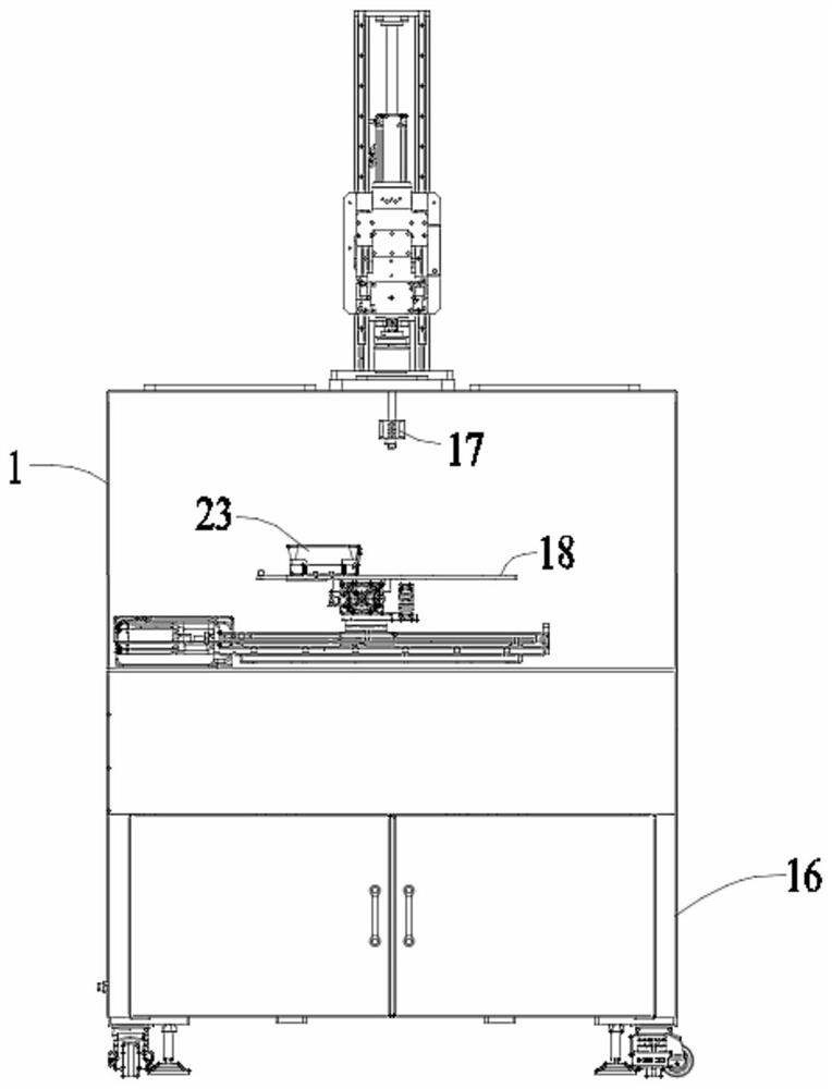
[0037] Example 1: A vacuum dispensing system, comprising a vacuum chamber body 1, a rack 16, a dispensing valve 17 and a workbench 18, the vacuum chamber body 1 is mounted on the rack 16, the dispensing valve 17 and The worktables 18 are all located in the vacuum chamber body 1, and the dispensing valve 17 is located directly above the worktable 18;

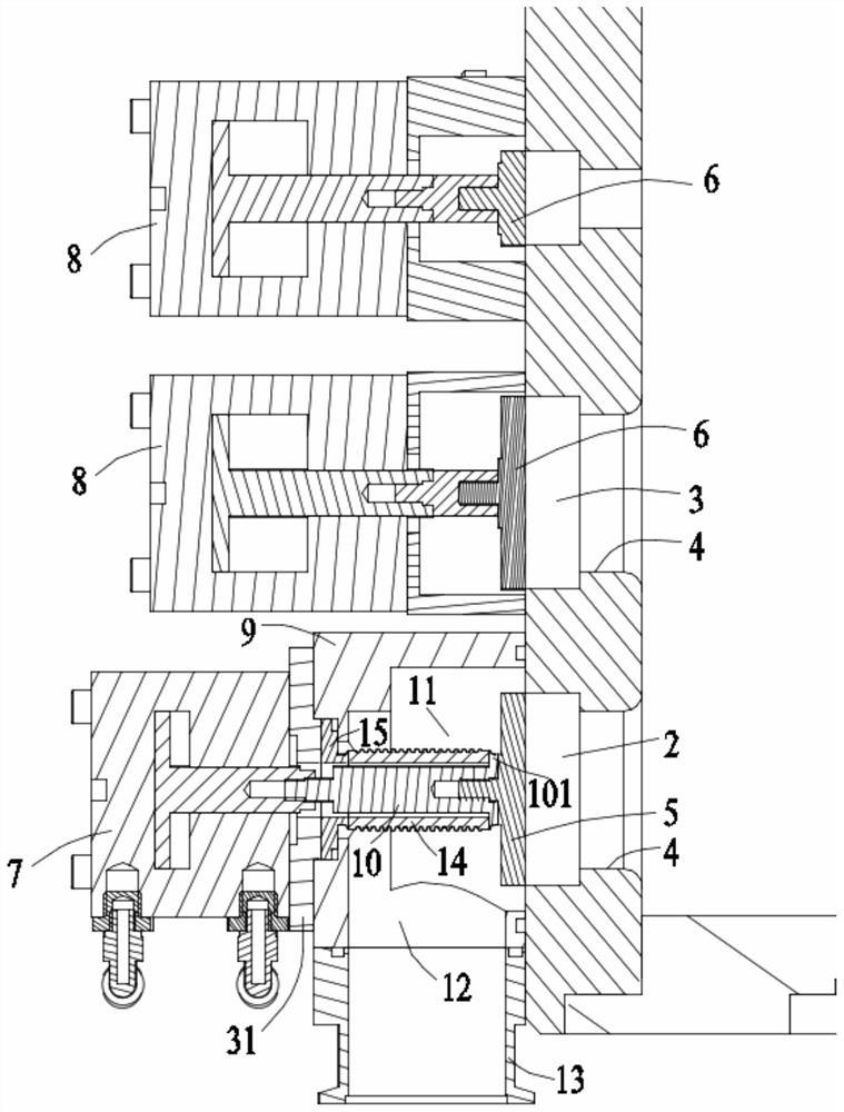
[0038] The outer surface of one side of the vacuum chamber body 1 is provided with an air outlet 2 and two air inlets 3, and the air outlet 2 and the air inlet 3 each have an inner wall near one end of the vacuum chamber body 1. The flange portion 4 protruding radially inward, a first flange 5 is embedded in the air inlet 2, a second flange 6 is embedded in the air inlet 3, and the first flange 5 is embedded in the air inlet 3. 5. The end face of one end of the second flange 6 is in contact with the end face of the corresponding flange portion 4, and the other ends of the first flange 5 and the second flange 6 are in contact with...

Embodiment 2

[0050] Example 2: A vacuum dispensing system, comprising a vacuum chamber body 1, a rack 16, a dispensing valve 17 and a workbench 18, the vacuum chamber body 1 is installed on the rack 16, the dispensing valve 17 and The worktables 18 are all located in the vacuum chamber body 1, and the dispensing valve 17 is located directly above the worktable 18;

[0051] The outer surface of one side of the vacuum chamber body 1 is provided with an air outlet 2 and two air inlets 3, and the air outlet 2 and the air inlet 3 each have an inner wall near one end of the vacuum chamber body 1. The flange portion 4 protruding radially inward, a first flange 5 is embedded in the air inlet 2, a second flange 6 is embedded in the air inlet 3, and the first flange 5 is embedded in the air inlet 3. 5. The end face of one end of the second flange 6 is in contact with the end face of the corresponding flange portion 4, and the other ends of the first flange 5 and the second flange 6 are in contact wi...


PUM


Abstract

The invention discloses a vacuum dispensing system, comprising a sealing chamber, a frame, a dispensing valve and a workbench. An air outlet and two air inlets are opened on the outer surface of one side of the vacuum chamber body. The flange is embedded in the air suction port, and a second flange is embedded in the air inlet. The piston rod of the cylinder is connected; the piston rod of the first cylinder and the first flange are connected through a first mandrel, an elastic member is sleeved on the first mandrel, and a scale is arranged on the worktable. The weighing mechanism includes a base installed on the workbench, a movable carrier plate installed on the upper part of the base, and a material cup placed on the upper surface of the movable carrier plate. The invention solves the problem that the electronic weighing equipment in the vacuum chamber is difficult to use, and avoids the situation that the waste glue overflows during the working process of the glue dispenser to contaminate the workbench or even damage the parts.

Description

technical field [0001] The invention relates to the technical field of vacuum cavity sealing, in particular to a vacuum dispensing system. Background technique [0002] The vacuum chamber is mainly used in the field of product dispensing and packaging. Using the force of negative pressure, the air in the vacuum box is first pumped away during the pouring process, and then the product is poured, which can quickly penetrate the glue into the product and inject shock. The bubbles generated by the contact between the glue and the product can also be quickly removed under the action of negative pressure, thus ensuring the high performance of the product. [0003] As the frequency of product updates and iterations continues to accelerate, the importance of the stability and efficiency of mass production equipment in the manufacturing industry is self-evident. In the process of controlling and distributing the fluid in the vacuum dispensing system, before the fluid in the mixing c...

Claims


Application Information

Patent Timeline
Patent Type & Authority Patents(China)
IPC IPC(8): B05C5/00B05C11/00
CPCB05C5/00B05C11/00
Inventor 陈晓峰杨春雨
Owner SUZHOU TERUITE ROBOT CO LTD
Why Eureka
Try Eureka