Flying second pulse simple real-time measuring instrument

A technology of real-time measurement and femtosecond pulses, applied in the field of femtosecond laser pulses, can solve the problems of complex operation of the SPIDER method, increase the difficulty of optical path adjustment, complex processing, etc., and achieve the effects of convenient optical path adjustment, compact structure, and simple optical path

Inactive Publication Date: 2007-01-03
SHANGHAI INST OF OPTICS & FINE MECHANICS CHINESE ACAD OF SCI
View PDF0 Cites 18 Cited by
  • Summary
  • Abstract
  • Description
  • Claims
  • Application Information

AI Technical Summary

Benefits of technology

This patented technology allows us to convert between two types of lights - one called red or green (R) rays that travel through air without being affected by external factors like weather conditions such as rain or snow. Instead we create special materials made up entirely from these waves, allowing them to change their properties depending upon how much they affect each other's waveform. By changing this material overall, our system provides technical means to improve measurements accurately while reducing costs compared to traditional methods.

Problems solved by technology

This patented technical problem addressed in this patents relates to improving the accuracy and efficiency of measuring femtonecence waves emitted from nanosecond lasers or similar sources without requiring cumbersome equipment. Current techniques involve either destructively analyzing each wave separately beforehand, or relying upon specific algorithms based on certain assumptions about its properties. These approaches have limitations due to their complexity and expense.

Method used


Image

  • Flying second pulse simple real-time measuring instrument
  • Flying second pulse simple real-time measuring instrument

Examples


Embodiment Construction

[0024] The present invention will be further described below in conjunction with drawings and embodiments.

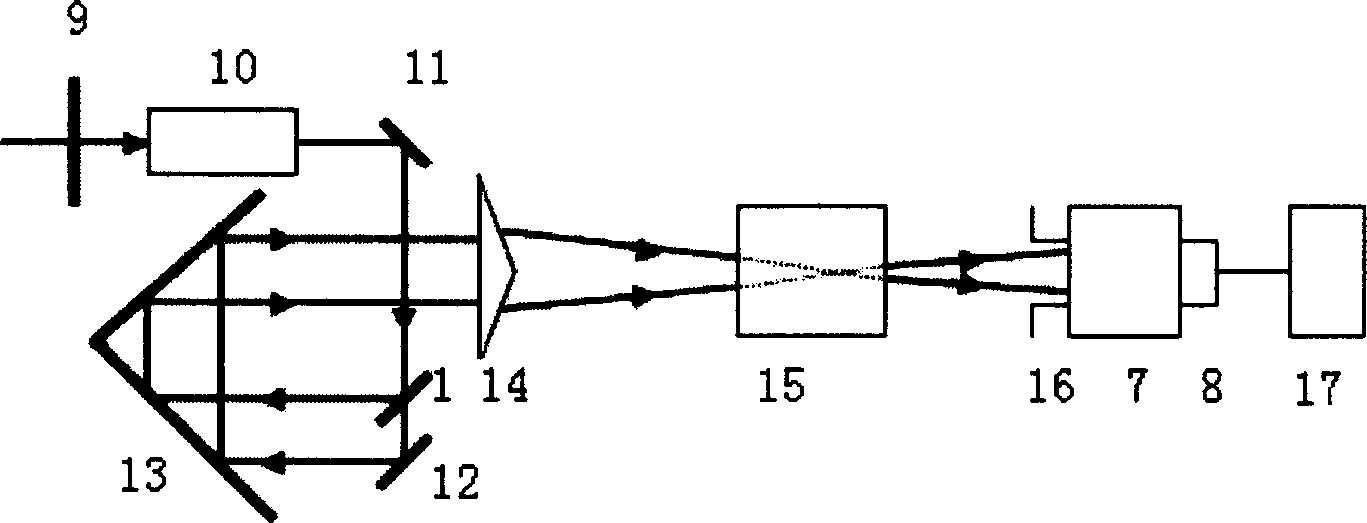
[0025] see first figure 2 , figure 2It is a structural schematic diagram of an embodiment of a simple real-time measuring instrument for femtosecond pulses of the present invention. As can be seen from the figure, the composition of the simple real-time measurement instrument for femtosecond pulses of the present invention is: along the advancing direction of the beam to be measured, it sequentially includes a half-wave plate 9, a quartz crystal 10, a beam splitter 1, a beam expander 13, and a large-angle Fresnel Double prism 14, thick nonlinear crystal 15, diaphragm 16, spectrometer 7, CCD detector 8 and computer 17, its positional relationship is: when the ultrashort pulse light beam to be measured of a horizontal polarization is vertically incident on described half-wave plate 9, the half-wave plate 9 divides the ultrashort pulse beam into e-light with horizontal...


PUM

PropertyMeasurementUnit
Top angleaaaaaaaaaa
Thicknessaaaaaaaaaa

Abstract

A simple real-time femtosecond pulse measure instrument, which uses ultrashort pulse spectrum phase interfere directive electric-field reconstruction method to measure, including: the half-wave board, the quartz crystal, the scattering beam installment, he scattering beam installment, the large-angle Fresnel biprism, the thick non-linear crystal, the diaphragm, the wavelength spectrometer, the CCD detector and the computer, the advantages of the invention are: the equipment of wiping off the femtosecond pulse grating width, the real-time measurement, the higher measuring precision and lower cost.

Description


Claims


Application Information

Patent Timeline
Owner SHANGHAI INST OF OPTICS & FINE MECHANICS CHINESE ACAD OF SCI
Why Eureka
Try Eureka