
Heat radiation fan

A heat dissipation fan and fan blade technology, which is applied in the direction of instruments, electrical digital data processing, digital data processing components, etc., can solve the problems of flow loss and other problems

Inactive Publication Date: 2006-12-27
FU ZHUN PRECISION IND SHENZHEN +1
View PDF0 Cites 4 Cited by
  • Summary
  • Abstract
  • Description
  • Claims
  • Application Information

AI Technical Summary

Problems solved by technology

[0004] With the continuous increase of heat density, the performance requirements of the fan are also increasing day by day, and because the air volume, wind pressure and the noise generated by the fan are contradictory, in the existing optimized design of the fan, it is generally under the noise standard. , to improve the performance of the fan by increasing the speed or increasing the size to meet the heat dissipation requirements. However, even under the optimal combination of various parameters, the internal flow field of the fan still has flow loss during operation. Therefore, how to improve the existing fan mechanism, Reducing the flow loss inside the fan and improving the performance of the fan has become the key to the design of the existing fan

Method used


Image

  • Heat radiation fan
  • Heat radiation fan
  • Heat radiation fan

Examples


Embodiment Construction

[0012] Hereinafter, further description will be made with reference to the drawings and the embodiments.

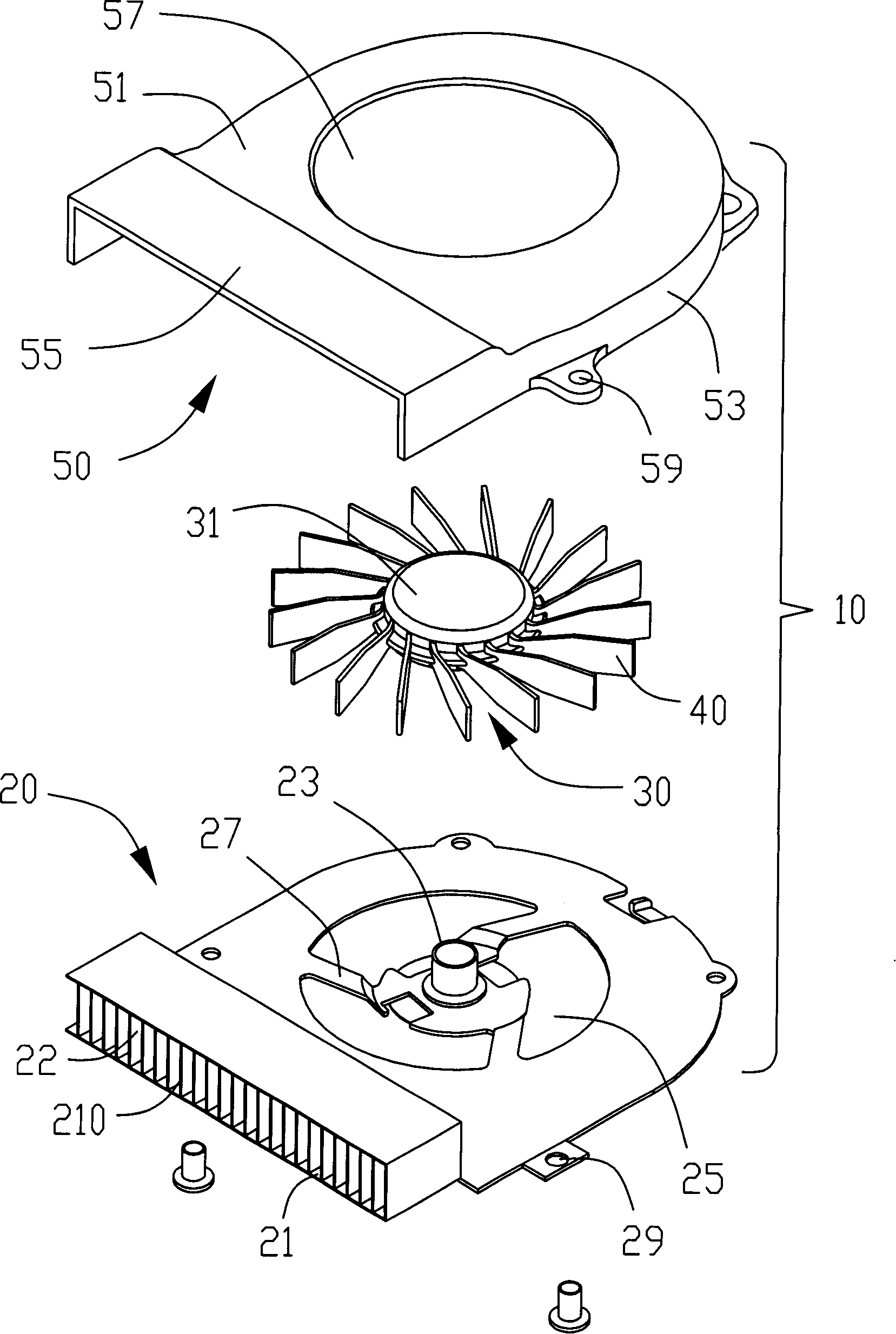
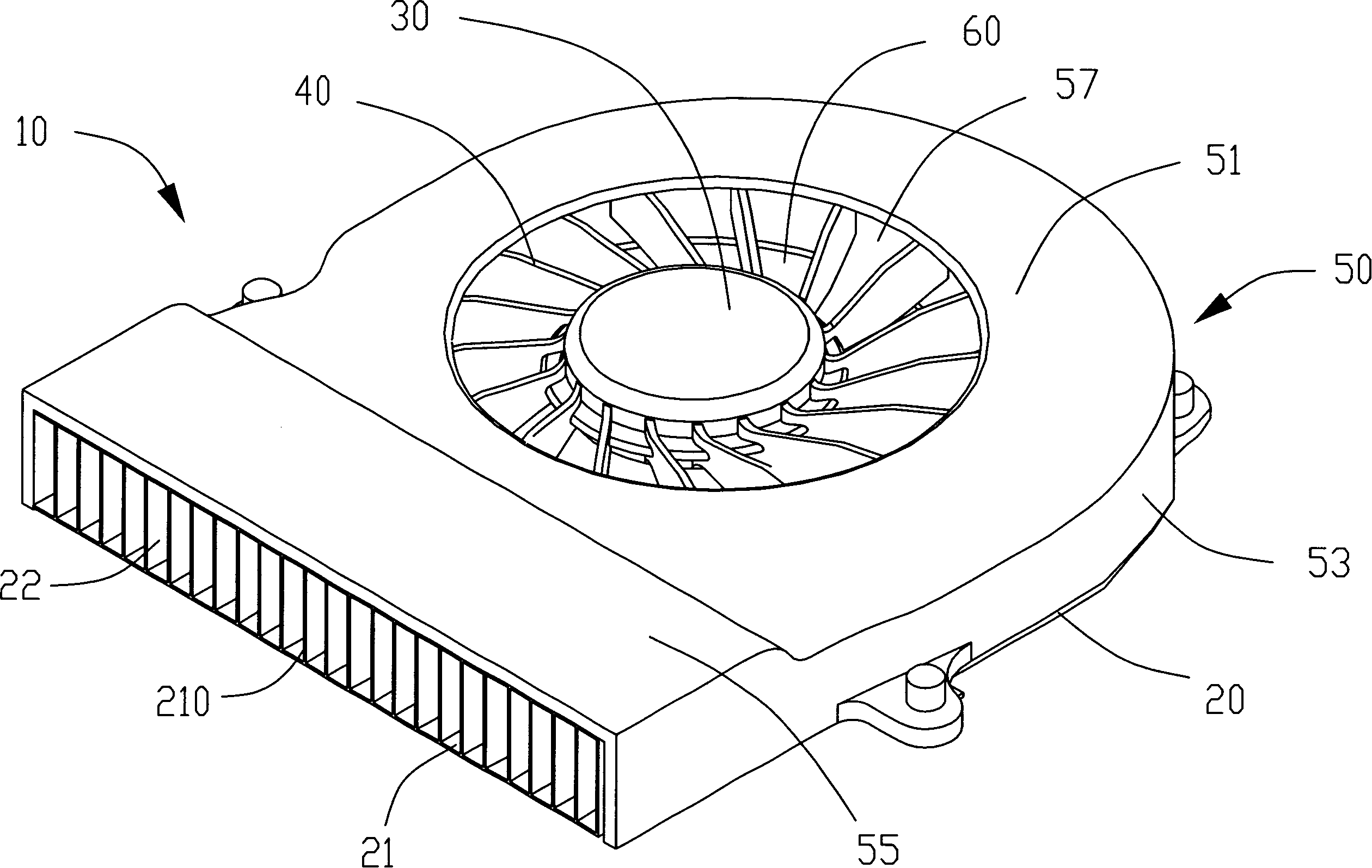
[0013] Such as figure 1 As shown, the cooling fan 10 includes a base 20, a motor 30 arranged on the base 20, a plurality of fan blades 40 arranged around the outer edge of the motor 30, and a cover arranged on the motor 30 and the fan blades 40上盖50。 Upper cover 50.

[0014] The upper cover 50 includes a top surface 51 and a side wall 53 extending downward from the top surface 51. The side wall 53 and the top surface 51 extend along the tangential direction of the upper cover 50 to form a "ㄇ"-shaped frame 55. A circular air inlet 57 is formed on the surface 51, and the outer edge of the side wall 53 is provided with a plurality of flanges, and each flange is provided with a through hole 59 for fixing the upper cover.

[0015] The base 20 is matched with the upper cover 50. The base 20 is roughly circular. Both sides of the base 20 extend along the tangential direction at the ...


PUM


Abstract

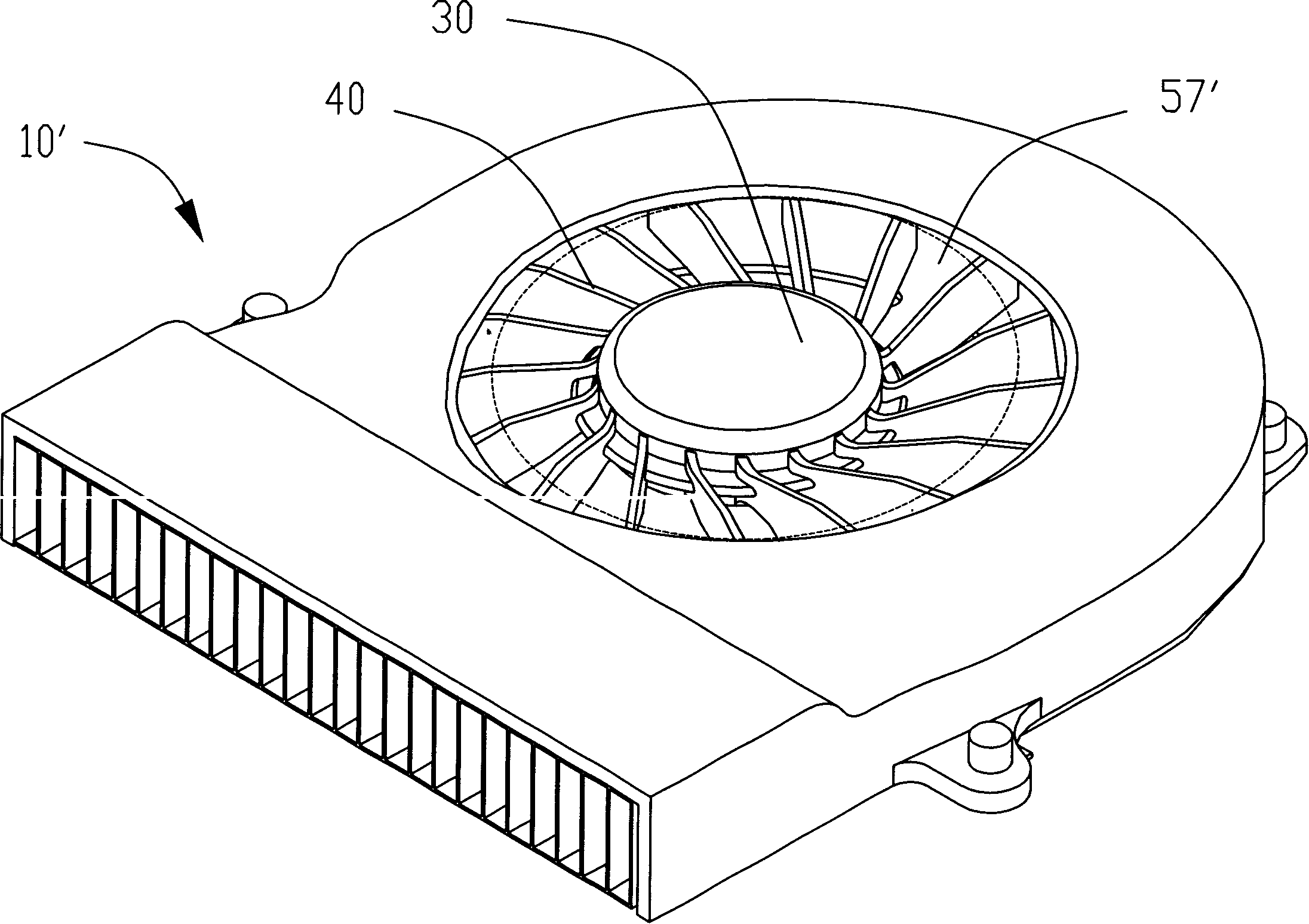
The invention relates to a radiation fan, which comprises a base, an upper cover, a motor and several leaves annularly arranged at the edge of motor, wherein said base and upper cover form one containing space to contain the motor and leaves; the upper cover has one wind inlet; the side end of radiation fan has wind outlet vertical to the wind inlet; each point of the edge of wind inlet and the central point of motor form different distances, to effectively reduce the airflow vortex loose and improve the fan property.

Description

【Technical Field】 [0001] The present invention is related to heat dissipation, and particularly refers to an efficient heat dissipation fan. 【Background technique】 [0002] With the continuous development of electronic technology, electronic components are developing in the direction of increasingly miniaturization and high density. The heat generated by the operation of electronic components (such as central processing units) is increasing. If the heat is not removed in time, it will lead to accumulation of heat. Causes the temperature to rise, which seriously affects the normal operation of electronic components. Generally, the industry installs a radiator on the electronic component to assist its heat dissipation, and installs a fan on the radiator to form a heat sink. The forced airflow is generated by the fan to quickly heat the radiator. Dissipate, thereby taking away the heat generated by the electronic components. [0003] Fans currently used in computers are roughly divi...

Claims


Application Information

Patent Timeline
Patent Type & Authority Applications(China)
IPC IPC(8): F04D29/44G06F1/20
CPCF04D29/4226F04D29/4213
Inventor 黄清白朱习剑张国文
Owner FU ZHUN PRECISION IND SHENZHEN
Learn More