
Pneumatic tool with improved structure

An air tool and air chamber technology, applied in the field of air tools with improved structure, can solve problems such as unfavorable production and increased difficulty in the assembly process.

Inactive Publication Date: 2006-12-20
MIGHTY SEVEN INT
View PDF1 Cites 7 Cited by
  • Summary
  • Abstract
  • Description
  • Claims
  • Application Information

AI Technical Summary

Problems solved by technology

[0006] The purpose of the present invention is to overcome the deficiencies and defects of the prior art, and propose a pneumatic tool with improved structure. The technical problem to be solved is that the outer casing of the existing structure must be arranged in the body in a tightly fitting manner, It is not integrally formed by the body, which makes the assembly process more difficult, which is not conducive to mass production in the industry

Method used


Image

  • Pneumatic tool with improved structure
  • Pneumatic tool with improved structure
  • Pneumatic tool with improved structure

Examples


Embodiment Construction

[0046] Regarding the technology, means and effects used in the present invention, a preferred embodiment is given and described in detail below with accompanying drawings, which are for illustration purposes only, and are not limited by this structure in patent applications.

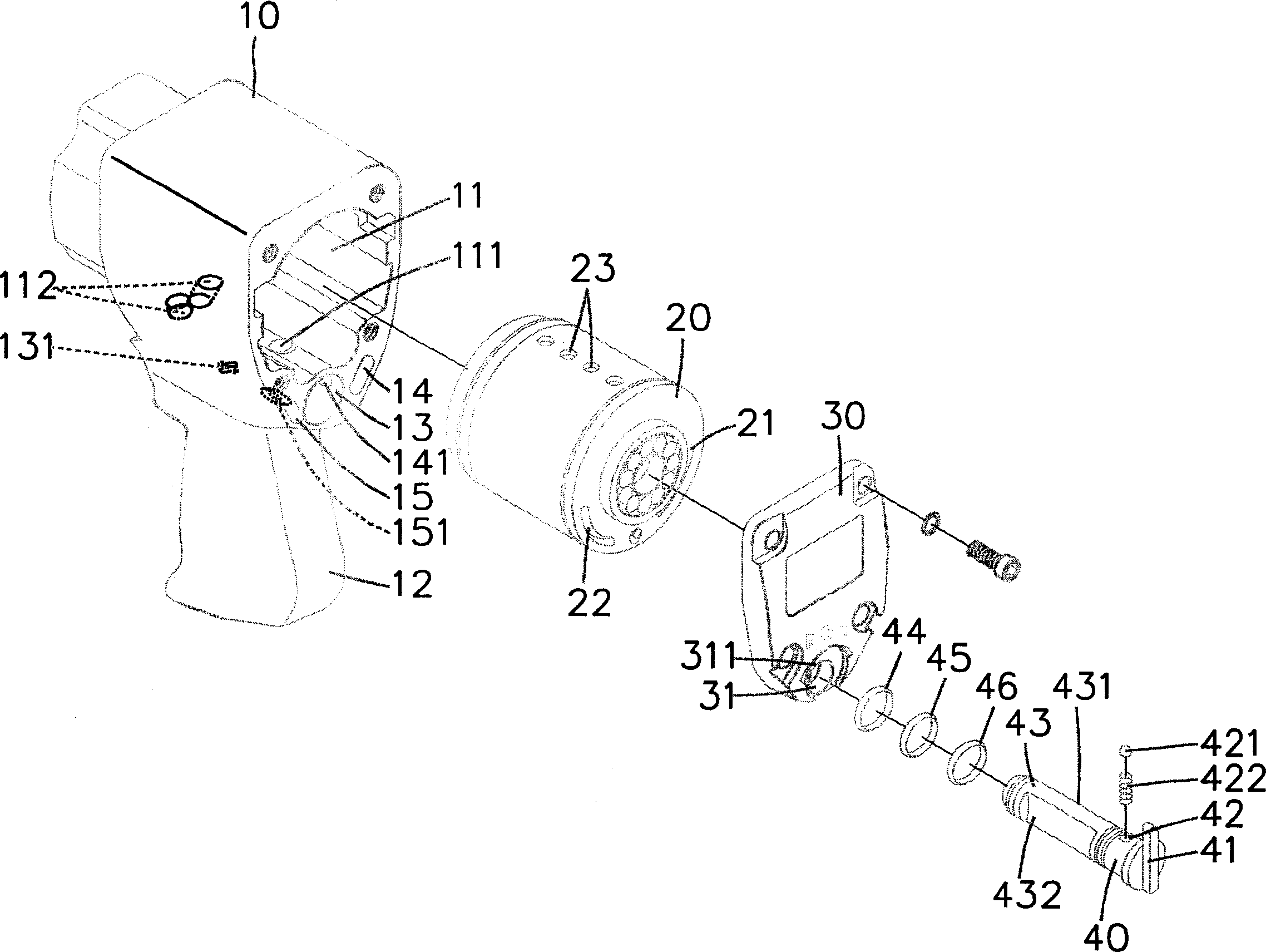
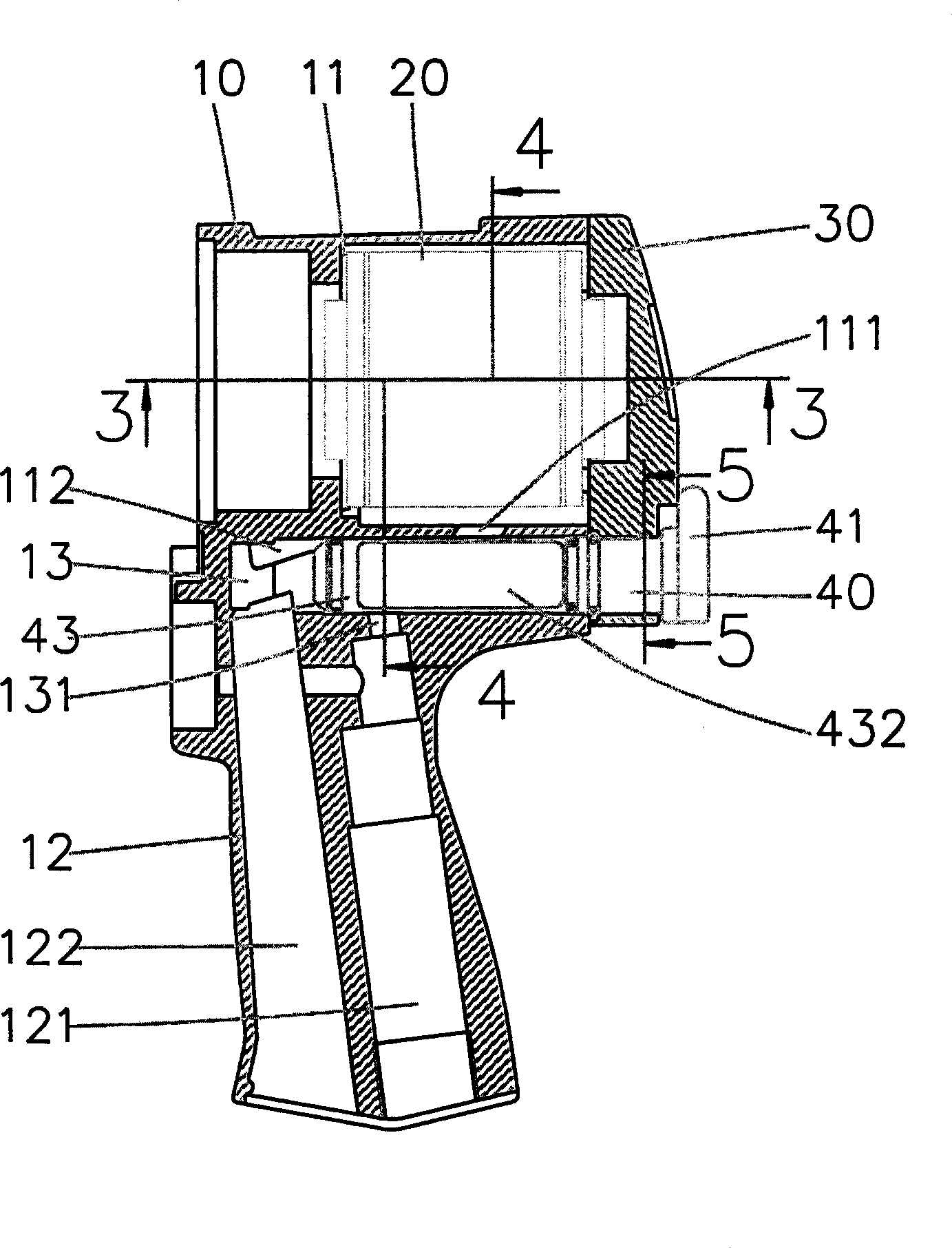
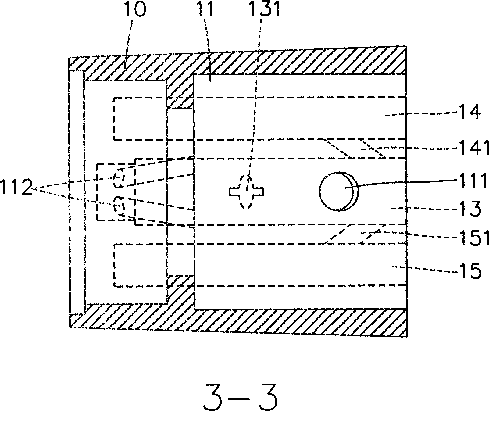
[0047] refer to Figure 1 to Figure 3 , the present invention includes a body 10, a cylinder block 20, a cover 30 and a control member 40; the body 10 is provided with a cross-shaped flow control hole 13, the cylinder block 20 is located in the body 10, the seal The cover 30 is used to close the cylinder group 20, and the control member 40 can cooperate with the flow control hole 13 to adjust the rotation speed and steering direction of the cylinder group 20, and the two sides of the control member 40 are provided with an axially extending Moreover, the non-intersecting forward rotation guide groove 431 and reverse rotation guide groove 432 can effectively simplify the manufacturing process and further r...


PUM


Abstract

The invention relates to an air powered tool, which comprises: a main body, a cylinder group, a sealing cover and a controller, wherein the main body has air room, control groove, and positive rotation air channel and passive rotation air channel connected to two sides of control groove; said control groove is arranged with flux control hole with cross shape; the cylinder group is inside the air room, whose one end has positive outlet and passive outlet; said sealing cover is at the air room, while it has one through hole at the position opposite to the control groove; the part of sealing cover near the main body has the positive air groove connecting the positive air channel and the positive outlet, and a passive air groove connecting passive rotation air channel and the passive outlet; one end of controller is axially arranged on the through hole of sealing cover to extend into the control groove of main body; two sides of controller are independently arranged with the positive and passive guide grooves that axially extending and not crossed; positive and passive guide grooves can be processed easily, to simplify the process and reduce producing cost.

Description

technical field [0001] The invention relates to a structurally improved pneumatic tool, especially the structurally improved pneumatic tool with simplified manufacturing process and reduced production cost. Background technique [0002] The structure of society is changing with each passing day. The quality of life that people demand is relatively improved, and the requirements for things have changed from the old thinking of "just use it" to a very delicate one. Only the concept of continuous improvement or innovation can satisfy the modern society. demand. [0003] Please refer to the TW Patent Announcement No. 513992 "Air Guide Structure Improvement of Pneumatic Tools" patent case, which is an existing structure of a pneumatic tool, mainly setting an outer casing on the body, and passing a rotary switch in the outer casing , and achieve the function of adjusting steering and adjusting speed. Although the existing structure has no major problems in use, it poses a consid...

Claims


Application Information

Patent Timeline
IPC IPC(8): B25F5/00B25B21/00B25C1/04B25C5/13B25D9/00B23B45/04
Inventor 张瑞昇
Owner MIGHTY SEVEN INT
Learn More