Annular binding member

A binding and ring technology, applied in binding, folder, printing and other directions, can solve the problems of large width and size of base parts, difficulty in ensuring quality stability, and difficulty in design and production, and achieve simple structure and structural strength. And the effect of improving quality stability and realizing design and manufacturability

Inactive Publication Date: 2006-12-13
KING JIM CO LTD
View PDF2 Cites 5 Cited by
  • Summary
  • Abstract
  • Description
  • Claims
  • Application Information

AI Technical Summary

Problems solved by technology

[0005] However, in the method of sliding one support member of the ring piece sideways, there is a problem that the opening of the ring cannot be increased without increasing the sliding amount of the support member.
In addition, there is also a method of sliding both ring pieces to the side of the base member, but according to this method, the following problems will arise: the width dimension of the base member will be enlarged due to the inclusion of the sliding mechanism, or the It is difficult to smoothly open and close the ring due to the influence of the weight of the bound document, etc.
Therefore, in order to realize the smooth action of the ring opening and closing mechanism, it is necessary to carefully select a material with good sliding properties, or carefully adjust the shape of the guide groove 28 and the protrusion 133, etc., so that it is difficult to design and manufacture, and it is difficult to ensure quality. stability problem
[0014] In addition, in such a structure in which the ring member 115 is rotated by the guide groove 28 and the protrusion 133, the guide groove 28 needs to be provided on the side surface of the slide member 113, so that there is a problem that the mold is complicated and the manufacturing cost is increased.

Method used


Image

  • Annular binding member
  • Annular binding member
  • Annular binding member

Examples


Embodiment Construction

[0048] Preferred embodiments of the present invention will be described below with reference to the drawings.

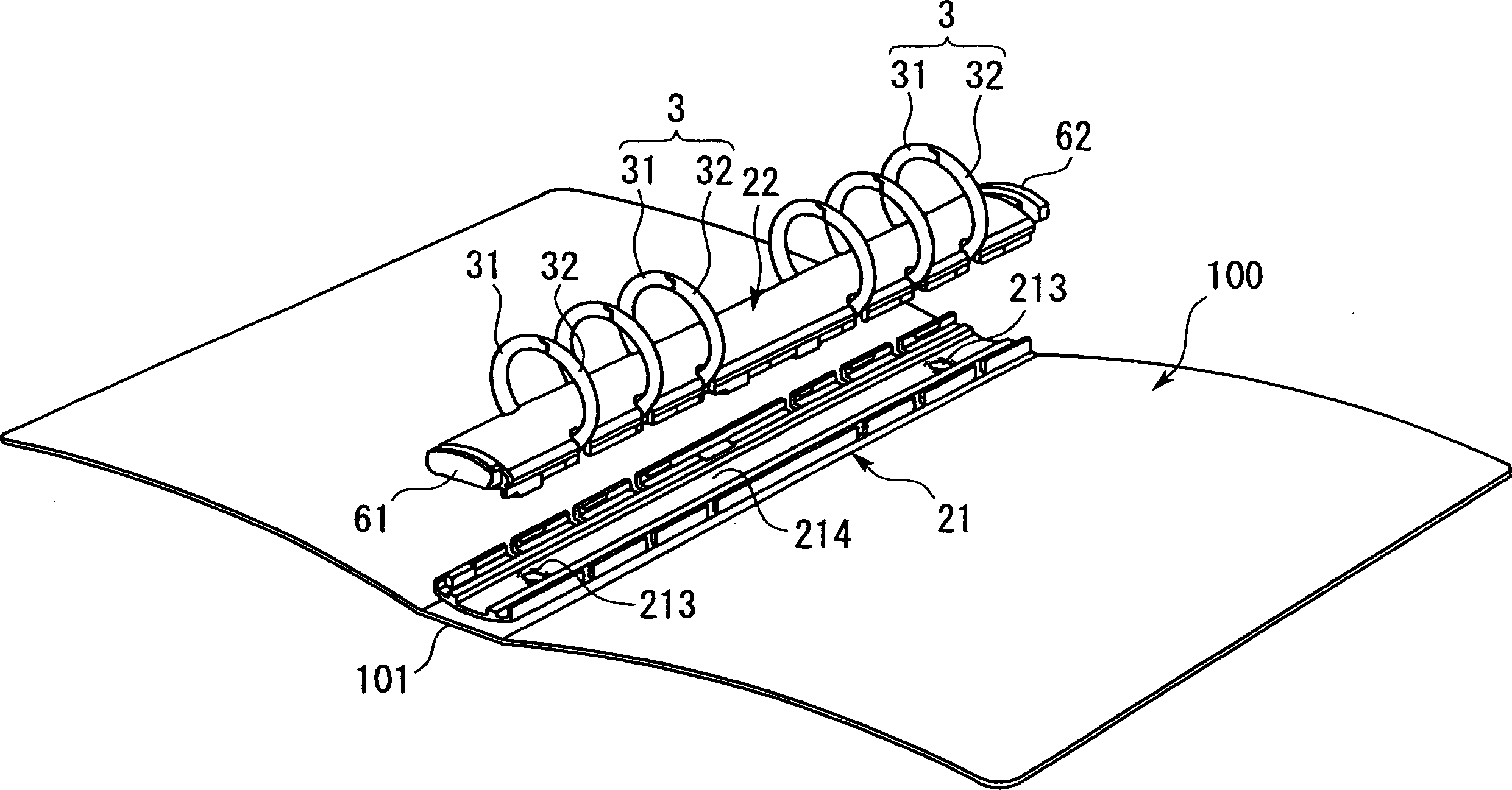
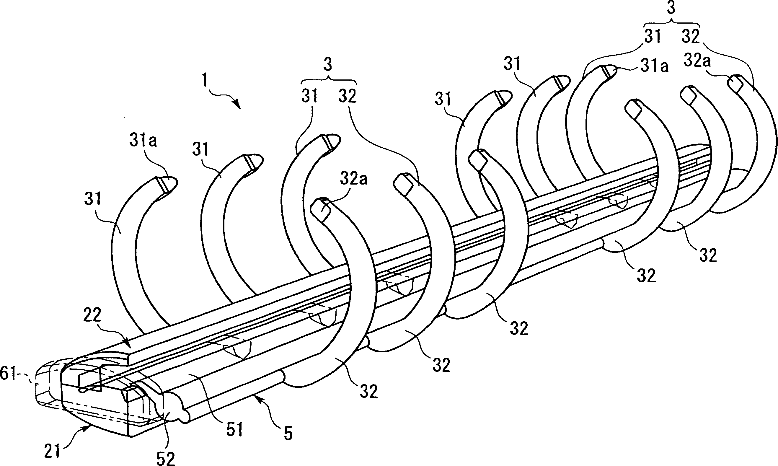
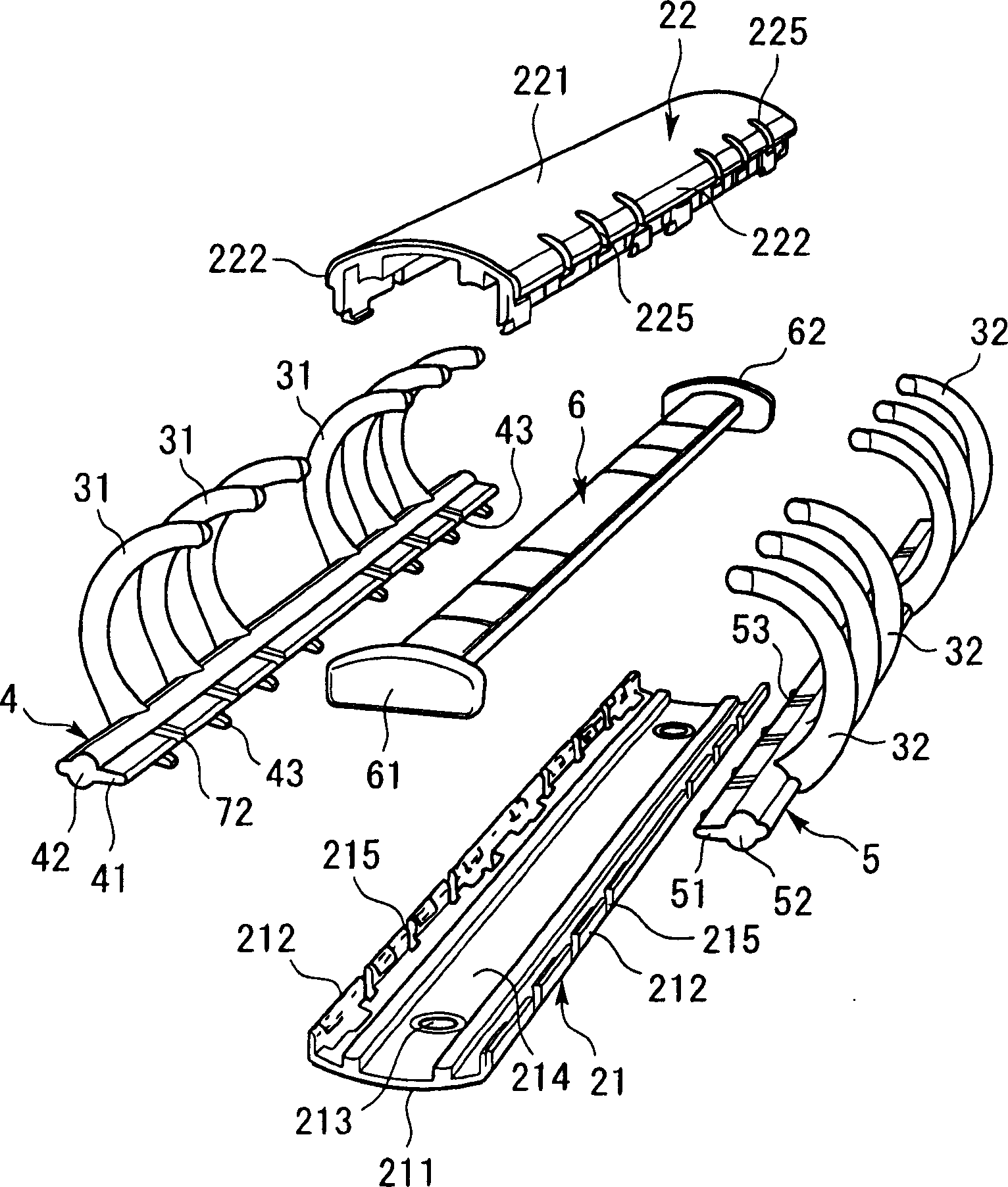
[0049] figure 1 It is a perspective view showing an embodiment in which the ring binder of the present invention is fixed to the spine cover of the cover body and used. figure 2 It is a perspective view which partially sees through and shows a ring binder. image 3 and Figure 4 is an exploded perspective view of the binder.

[0050] The ring binder 1 of the present embodiment is provided with: a base part 2 (refer to Figure 6 ), a plurality of (six) rings 3 arranged at intervals along the length direction of the base portion 2, two ring support members (the first support member 4 and the second support member 4 and the second support member) arranged in parallel in the base portion 2 member 5), an operating member 6 arranged to be capable of reciprocating movement along the longitudinal direction of the base portion 2, and a switching mechanism 7 for opening ...


PUM


Abstract

The invention provides a ring-type stapling device which comprises: a base part (2) with shell shape; plural rings (3) set on the base part, changing ring-closure posture and ring-opening posture by contacting or getting far away of the free ends of one side-ring and the other side ring; a first supporting component (4) for supporting one side ring and a second supporting component (5) for supporting the other side ring, which are installed in the base part; an operation component (6) which can move forth and back along the length of the base; a switching structure set among the first supporting component, the second supporting component and the operation component, which makes the first and the second supporting components lean around the base part when the operation component moving back and forth so that the ring can switch postures between ring-closure and ring-opening.

Description

technical field [0001] The present invention relates to a technique of a ring binder for binding loose pages and the like provided with a plurality of binding holes along one edge. Background technique [0002] A ring binder including a plurality of openable and closable rings is conventionally known. For example, it is often used as a binder for binding loose-page photo albums, memo pads, notebooks, transparent film storage bags, and the like. [0003] Such a ring binder generally opens and closes the rings by performing an operation of fitting or separating free ends of left-right symmetrical or asymmetrical semicircular ring pieces. [0004] As a method of opening and closing a ring, Patent Document 1 describes a technique of opening and closing a ring by sliding operation of a sliding member. This technique is as follows: by sliding one of two supporting members that respectively support the left and right ring pieces to the side of the base member, the rings are broug...

Claims


Application Information

Patent Timeline
Patent Type & Authority Applications(China)
IPC IPC(8): B42F13/22B42F3/04
Inventor 岛田博藤田哲也可児友靖
Owner KING JIM CO LTD
Why Eureka
Try Eureka