Manuscript pressure plate opening and closing device and office equipment with the same
A technology of original pressing plate and opening and closing device, which is applied in the direction of wing leaf opener, wing closer, and switch with braking device, etc., which can solve the problems of rising costs and achieve smooth opening and closing operations, good operability, The effect that a feeling of opening and shutting is good
- Summary
- Abstract
- Description
- Claims
- Application Information
AI Technical Summary
Problems solved by technology
Method used
Image
Examples
Embodiment 1
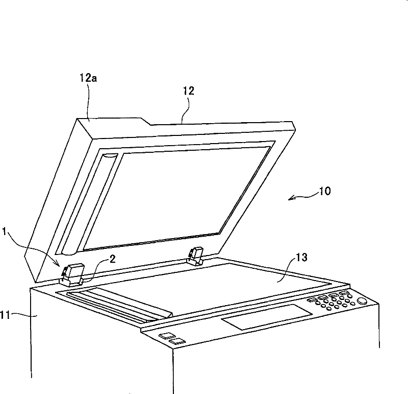
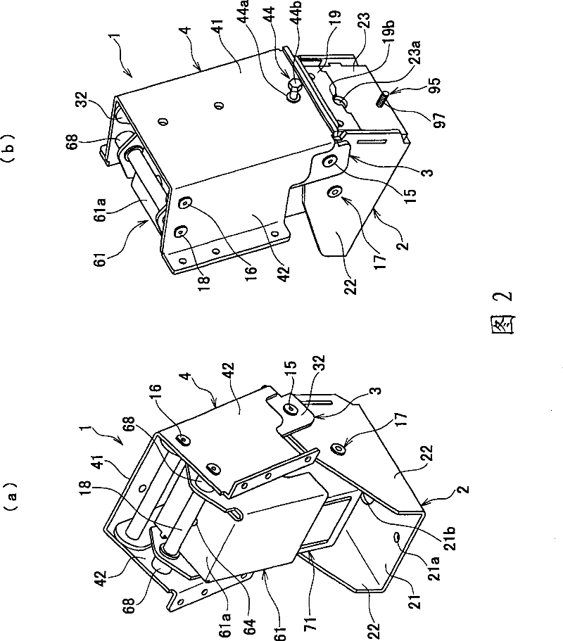
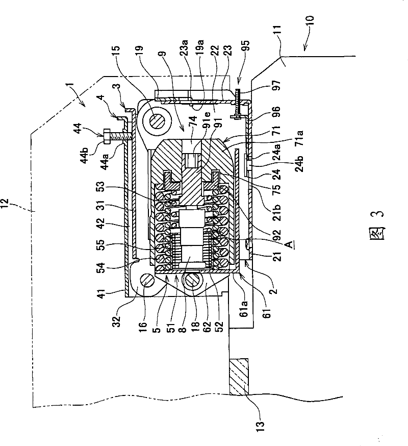
[0046] Figure 1 to Figure 5 It is a diagram showing an example of the document pressure plate opening and closing device of the present invention. Such as figure 1 As shown, the document presser opening and closing device 1 of the present invention is a device in which a document presser 12 is rotatably attached to the rear of the upper surface of the main body 11 of the office equipment 10 . The office equipment 10 is not particularly limited, and examples thereof include copiers, printing machines, facsimile machines, scanners, and the like. In particular, a copier is mentioned as a preferable example, but it will be described without particular limitations. In addition, as shown in the figure, a pair of original pressing plate opening and closing devices 1 are usually used. Regarding the device for opening and closing the original pressing plate 12 with the automatic original feeding device 12a, a heavy automatic original feeding device is equipped on the left side due to...
Embodiment 2
[0087] Figure 15 and Figure 16 Another embodiment of the document presser opening and closing device is shown. According to the drawings, in the document presser opening and closing device 99 of this embodiment, one of the parts existing at both ends of the elastic member 100 is a cam slider 104, and the other is a cam slider. One side is the slider 107. The cam slider 104 is configured to be slidably surrounded by the support member 101, and the front end is in contact with the pressure receiving member 103 mounted on the mounting member 102. The slider 107 is also configured to be slidably supported by the member. 101 surrounds and is in sliding contact with the working part 106 installed on the free end side of the lifting part 105, and the elastic force adjustment member 108 of the middle-diameter compression coil spring 100b located inside the large-diameter compression coil spring 100a in the elastic member 100 is installed on the sliding body On the 107 side, the dam...
Embodiment 3
[0089] In the case of this embodiment 3, the original platen opening and closing device 111 can also be configured to omit the sliding body 107 in the previous embodiment 2, such as Figure 17 As shown, a top plate 112b suspended from the top plate 112a of the support member 112 is provided, and an elastic member 115 is elastically provided between the top plate 112b and the cam slider 114 provided on the mounting member 113 side. Furthermore, an elastic force changing member A is provided in the compression coil spring constituting the elastic member 115 . Moreover, the number and diameter of the compression coil springs are not limited by the embodiment. In addition, regarding the damper member 119, there are cases where this member is provided and cases where this member is not provided. Also, the same parts as other index marks represent the same components as in the second embodiment.
[0090] In the case of the third embodiment, the second hinge pin 117 is used to inst...
PUM
 Abstract
Description
Claims
Application Information
 - R&D
- Intellectual Property
- Life Sciences
- Materials
- Tech Scout
- Unparalleled Data Quality
- Higher Quality Content
- 60% Fewer Hallucinations
Browse by: Latest US Patents, China's latest patents, Technical Efficacy Thesaurus, Application Domain, Technology Topic, Popular Technical Reports.
© 2025 PatSnap. All rights reserved.Legal|Privacy policy|Modern Slavery Act Transparency Statement|Sitemap|About US| Contact US: help@patsnap.com


