
Electric drive unit for generating an oscillating displacement

A drive unit, oscillating motion technology, applied to electrical components, reciprocating/oscillating/vibrating magnetic circuit components, electromechanical devices, etc., can solve problems such as changing and undesired excitation frequencies

Inactive Publication Date: 2006-12-06
BRAUN AG
View PDF2 Cites 3 Cited by
  • Summary
  • Abstract
  • Description
  • Claims
  • Application Information

AI Technical Summary

Problems solved by technology

But such adjustment requires additional manufacturing costs
Also, in some applications it is not desirable to change the excitation frequency

Method used


Image

  • Electric drive unit for generating an oscillating displacement
  • Electric drive unit for generating an oscillating displacement
  • Electric drive unit for generating an oscillating displacement

Examples


Embodiment Construction

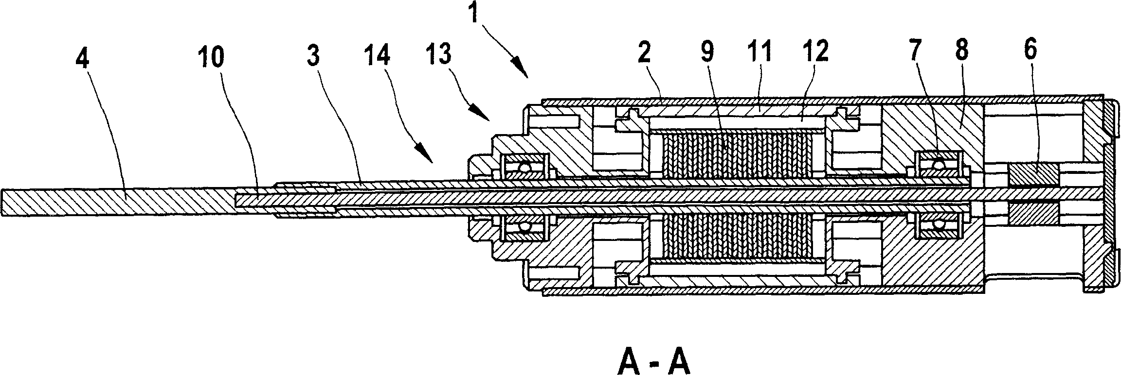
[0024] figure 1 A plan view of an exemplary embodiment of a drive unit 1 constructed according to the invention is shown. The drive unit 1 has a longitudinally extending housing 2 , from the end side of which a hollow shaft 3 protrudes, said hollow shaft being parallel to the longitudinal axis of the drive unit 1 . A connecting piece 4 for accommodating a toothbrush not shown in the figure is inserted coaxially into the axial end of the hollow shaft 3 outside the housing 2 and is connected in a rotationally fixed manner to the hollow shaft 3 . The housing 2 has a window-shaped gap 5 on one of its longitudinal sides in an end region remote from the end side of the hollow shaft 3 protruding from the housing 2 . Visible through the gap 5 is a slide 6 arranged in the interior of the housing 2 , which is displaceable parallel to the longitudinal axis of the drive unit 1 and will be described in more detail below. From Figure 2-5 sectional view or from the second embodiment of t...


PUM


Abstract

The invention relates to an electric drive unit (1) for generating an oscillating displacement. The inventive drive unit (1) comprises a stator (13), a rotor (14) and a torsion element (10) and is characterised in that it is equipped with a tuning element (6), which acts on the torsion element (10) to mechanically tune the resonant frequency of said drive unit (1).

Description

technical field [0001] The invention relates to an electric drive unit for generating an oscillating movement. Furthermore, the invention relates to a small electrical appliance having such a drive unit and a method for producing such a drive unit. Background technique [0002] Electric drive units for generating an oscillating movement are used, for example, in electric toothbrushes and electric shavers. An electric toothbrush with an oscillating rotor motor is therefore known from DE 28 20 437 A1. The rotor oscillating motor rotates the shaft on which the brush portion is mounted back and forth. The rotation is influenced by torsion springs and damping elements, so it is adjusted to the desired course of motion. [0003] An oscillating device, in particular an electric toothbrush, is known from US 5,613,259. The device has a mechanical oscillator driven by an electric motor. Depending on the vibration frequency of the mechanical oscillator detected by the sensor, the ...

Claims


Application Information

Patent Timeline
Patent Type & Authority Applications(China)
IPC IPC(8): H02K33/02A61C17/22A61C17/34B26B19/28H02K1/34
CPCH02K33/02B26B19/28H02K1/34A61C17/34A61C17/225Y10T29/49009
Inventor 格哈德·克雷斯纳亚历山大·施勒特尔克里斯蒂安·容克彼得·希尔芬格汉斯约尔格·赖克伯恩哈德·克劳斯乌韦·舍贝尔
Owner BRAUN AG
Learn More