
Gate in double arched structure

An arch structure and gate technology, applied in the field of gates, can solve the problems of high implementation cost, unreasonable force, large steel consumption, etc., and achieve the effects of reducing water flow resistance, uniform force, and reducing excitation

Inactive Publication Date: 2006-12-06
ZHEJIANG UNIV
View PDF0 Cites 5 Cited by
  • Summary
  • Abstract
  • Description
  • Claims
  • Application Information

AI Technical Summary

Problems solved by technology

However, when the current planar gate has a large span, it has the disadvantages of large steel consumption, heavy weight, high implementation cost and unreasonable force.

Method used


Image

  • Gate in double arched structure
  • Gate in double arched structure

Examples


Embodiment Construction

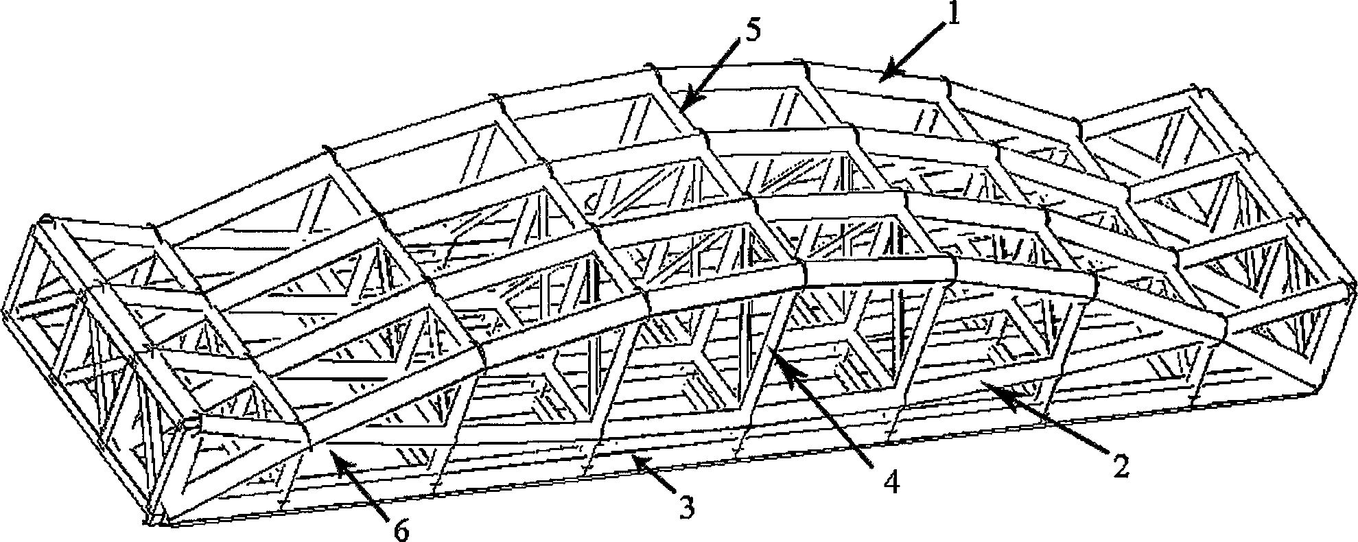
[0012] Such as figure 1 As shown, a fish belly-shaped double-arch structural component of a double-arch gate includes cross-arranged positive arches 1 and reverse arches 2, the cross-closed parts of the double-archs are shuttle-shaped, and the cross-open parts are fishtail-shaped. The two ends of the main arch 1 are connected by chords 3 . The positive arch 1, the reverse arch 2, and the chord 3 are connected through the web 4 perpendicular to the chord 3. The web members are arranged at least at the ends, intersections and middle parts of the double arches.

[0013] Such as figure 2 As shown in Fig. 1, the adjacent double-arch structure components are connected by transverse connecting rods 5, and the transverse connecting rods are arranged near the nodes where the arches and web members intersect, including cross bars connecting corresponding nodes and connecting non-corresponding nodes. Diagonal bar. The steel water-retaining panels 6 are directly welded outside the ch...


PUM


Abstract

A gate with double arch structure is prepared as connecting two ends of positive arch by chord; connecting positive arch, negative arch and chord by web member vertical to chord; applying horizontal connection rod to connect adjacent fish belly double-arch components and directly welding steel water-blocking plate at external of chord on each fish belly double-arch component.

Description

technical field [0001] The invention relates to a gate used in water conservancy projects, in particular to a planar gate with double-arch truss structure under bidirectional force, which is suitable for large gate structures with internal and external loads. Background technique [0002] The gates used in water conservancy projects are mainly divided into plane gates and arc gates at present, and what the present invention relates to are plane gates. The planar gate is a plate-shaped door leaf inserted into the door slot to block water. The form of the door leaf can be plate-shaped or shell-shaped, etc. It is opened and closed vertically by the hoist or at the bottom or top of the door leaf. Install traveling rollers to move laterally along the track. The specific structural form of the planar gate is as follows. Its panel is divided into many units of rectangular plates by the beam system. The panel bears all the water pressure, and then the pressure is transmitted to the...

Claims


Application Information

Patent Timeline
Patent Type & Authority Applications(China)
IPC IPC(8): E02B7/20
Inventor 罗尧治朱世哲沈雁彬
Owner ZHEJIANG UNIV
Learn More