
Container loading and unloading vehicle and container loading and unloading method

A technology for loading and unloading trucks and containers, which is applied to vehicles with cranes, etc., can solve the problem of not being able to load containers C2t, etc., and achieve the effect of reducing insurance premiums and improving safety.

Inactive Publication Date: 2006-12-06
TECHNO MIZUHO
View PDF5 Cites 7 Cited by
  • Summary
  • Abstract
  • Description
  • Claims
  • Application Information

AI Technical Summary

Problems solved by technology

Of course, a 4t container truck cannot load a C2t container

Method used


Image

  • Container loading and unloading vehicle and container loading and unloading method
  • Container loading and unloading vehicle and container loading and unloading method
  • Container loading and unloading vehicle and container loading and unloading method

Examples


Embodiment Construction

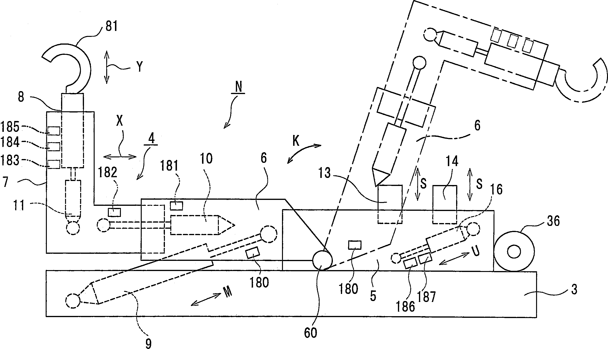
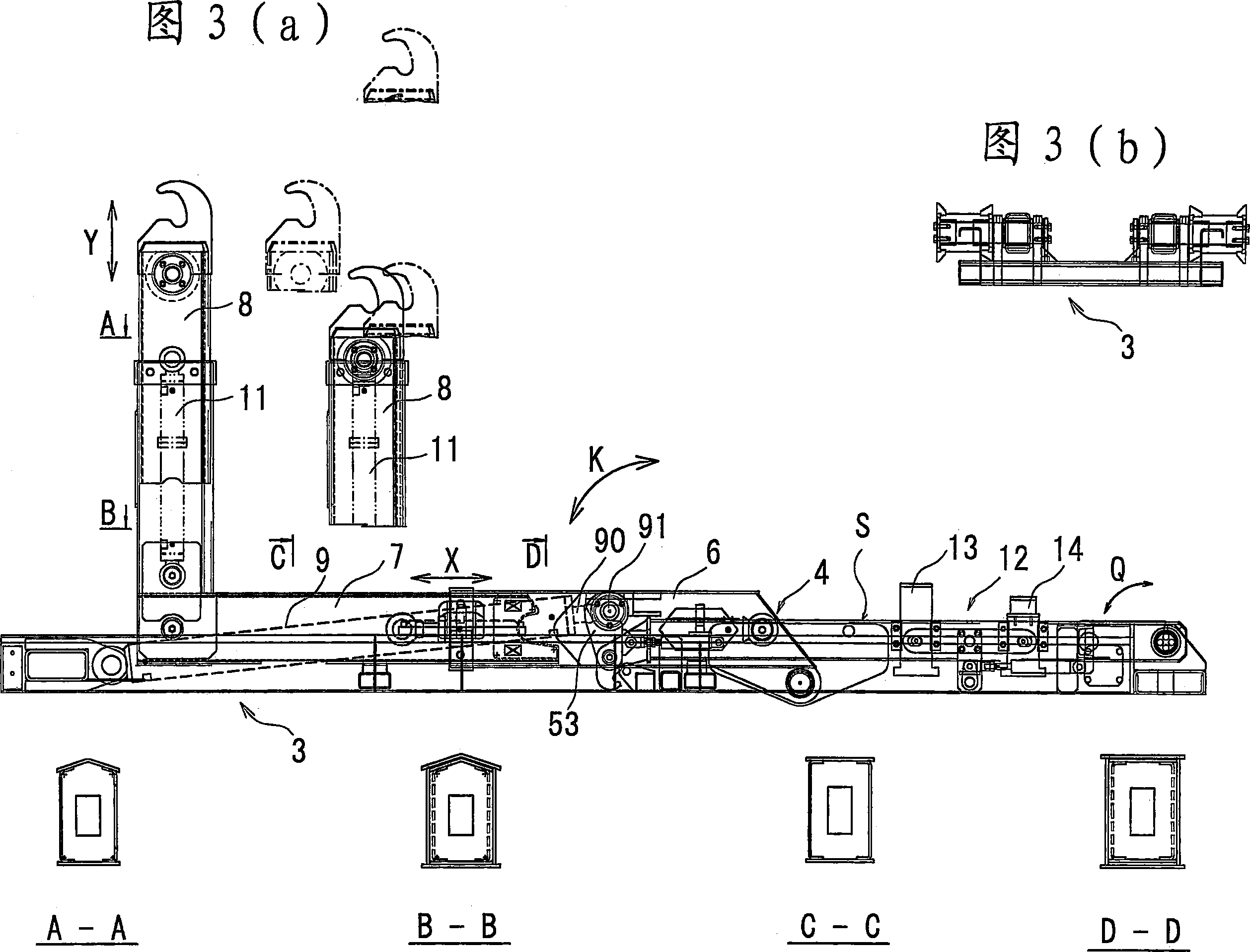
[0116] Hereinafter, a container handling truck 1 according to the best embodiment of the present invention will be described with reference to the drawings. The maximum loading capacity of the container handling truck 1 is 4t. The container loading and unloading truck 1 is equipped with a loading capacity of 8m 3 container (hereinafter referred to as container C4t) and the loading volume is 4m 3 The container (hereinafter referred to as container C2t) replaces the loaded structure. The main function and braking force of the container handling truck 1 are designed to travel under the loadable container C4t, and the car body structure is designed to also be able to load the container C2t. The loading state is different when the container C4t is loaded and when the container C2t is loaded (refer to FIG. 25 ).

[0117] Container handling truck 1 has figure 1 Cargo rack N shown. The cargo handling frame N has a main frame 3 installed on the vehicle body 2 and connects the main...


PUM


Abstract

The invention provides a method for loading counters with different loading volume to a counter loading and unloading vehicle alternatively. The counter loading and unloading vehicle can load counter with loading volume being 8m3 / SUP and 4m 3 B60P 1 / 54 43 23 5 2006 / 2 / 20 1872584 2006 / 12 / 6 100497042 2009 / 6 / 10 2009 / 6 / 10 2009 / 6 / 10 Ruisui Co., Ltd. Japan Kitsukawa Hirokuni sun haochen 11139 Japan 2005 / 2 / 21 JP2005-44561 Japan 2005 / 5 / 23 JP2005-149599 Japan 2006 / 1 / 25 JP2006-16943

Description

technical field [0001] The invention relates to a container loading and unloading vehicle with a main frame on the vehicle frame and a rotatable bracket for the main frame, and a container loading and unloading method on the bracket. Background technique [0002] Fig. 43 is a diagram illustrating a container handling truck of Patent Documents 1 to 3, which has a main frame 3' mounted on a vehicle body 22', and is loaded on a bracket 4 provided on the main frame 3'. A structure that loads and unloads containers Ct of a specified loading volume. [0003] The bracket 4 shown in Figure 43 (a) is a dumping frame 5' that is extended to one side (left and right of Figure 43) of the vehicle body length of the vehicle body F', and the dumping frame 5 'The support arm 6' which is rotatably connected to the front and extends to the longer side of the vehicle body, and the sliding arm 7' which is connected to the front of the support arm 6' and extends up and down. [0004] There is a...

Claims


Application Information

Patent Timeline
IPC IPC(8): B60P1/54
Inventor 吉川弘国
Owner TECHNO MIZUHO
Learn More