
Cooling system of portable equipment

A technology for portable equipment and cooling systems, applied in cooling/ventilation/heating renovation, instruments, electrical digital data processing, etc. Satisfaction level, the effect of reducing errors

Inactive Publication Date: 2010-04-28
LEJIN ELECTRONICS KUNSHAN COMPUTER CO LTD
View PDF4 Cites 0 Cited by
  • Summary
  • Abstract
  • Description
  • Claims
  • Application Information

AI Technical Summary

Problems solved by technology

The result is not suitable for overall system cooling
[0006] In addition, in the conventional technology, the cooling fan is operated only according to the heating temperature of the CPU to achieve the purpose of controlling cooling, but there is still a limitation in reducing the overall heating of the system. As a result, users who are sensitive to the temperature of the system itself often there will be dissatisfaction

Method used


Image

  • Cooling system of portable equipment
  • Cooling system of portable equipment
  • Cooling system of portable equipment

Examples


Embodiment Construction

[0025] The cooling system of the portable device of the present invention will be described below.

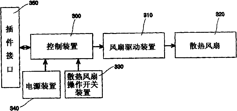
[0026] figure 1 It is a control configuration diagram of the cooling system drive of the portable device of the present invention.

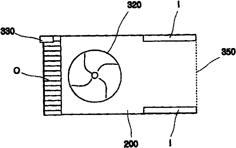
[0027] The control structure of the cooling system of the present invention includes the following devices: a power supply unit 340 that provides power to the interior of the portable device; a cooling fan 320; a fan drive unit 310 that drives the cooling fan 320; a cooling fan configured in the plug-in for inputting the cooling fan operation signal The operation switch device 330; the control device 300 for controlling the portable device and operating the cooling fan according to the input cooling fan operation signal; and the plug-in interface 350 for receiving and sending plug-in data.

[0028] After the plug-in with cooling fan 320 is installed in the plug-in slot of the portable device, the cooling fan operation switch device 330 is turned ...


PUM


Abstract

A cooling system of portable device comprises signal input unit, air inlet hole, air outlet hole, heat sink in plug-in unit erected in portable device, fan driving unit and control unit for control operation of heat sink. It is featured as having heat sink operated continuously only by setting said plug-in unit electric-connected with heat sink so as to regulate temperature ambient in said systemto be optimum state.

Description

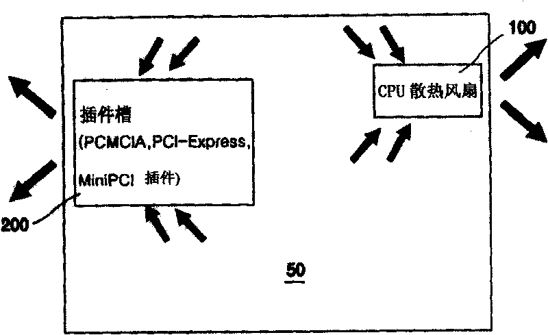
technical field [0001] The present invention relates to a cooling system of a portable device, in more detail, to a cooling system of a portable device equipped with a cooling fan in a card used in the portable device. Background technique [0002] The cooling system of the portable device according to the prior art is equipped with a cooling fan dedicated to the CPU for reducing the heat generated by the CPU inside the portable device. Generally speaking, the CPU generates a lot of heat due to its characteristics. Therefore, it is necessary to install a dedicated cooling device for cooling the CPU, that is, a cooling fan is provided as a cooling device. [0003] In the prior art, in order to drive the heat dissipation fan, the heating temperature of the CPU is sensed, and then the driving of the heat dissipation fan is controlled according to the heat generation temperature. [0004] However, the conventional technology has the following problems because it uses the same c...

Claims


Application Information

Patent Timeline
Patent Type & Authority Patents(China)
IPC IPC(8): H01L23/467G06F1/20H05K7/20
Inventor 李镇硕
Owner LEJIN ELECTRONICS KUNSHAN COMPUTER CO LTD
Learn More