Hydroelectric power generator by means of circulating buoyancy and gravity

A hydroelectric power generation device, buoyancy technology, applied in the direction of hydroelectric power generation, engine components, machines/engines, etc., can solve problems such as environmental hazards

Inactive Publication Date: 2006-11-29
陈添泉
View PDF0 Cites 5 Cited by
  • Summary
  • Abstract
  • Description
  • Claims
  • Application Information

AI Technical Summary

Problems solved by technology

[0002] At present, there are many ways to obtain electricity, among which thermal power, hydraulic power, nuclear power and other power generation methods are the majority, and thermal power and nuclear power generation account for the heaviest and highest proportion of electric energy, but both of them need non-renewable energy sources, such as coal, Petroleum, liquefied natural gas, etc. are used as energy generation media, and though these non-renewable energy sources can quickly and effectively obtain energy and convert it into electrical energy, but judging from the current widespread use, in the near future, These non-renewable energies will be exhausted. Moreover, the awareness of environmental protection is gradually rising, and these non-renewable energies will cause harm to the environment. Therefore, many fields that use non-renewable energies are gradually moving towards Develop renewable and recyclable energy sources, and gradually use solar energy, wind power, ocean tides, ocean currents, etc. to obtain electric energy, but there are various limitations and limitations of climate, terrain, and geographical location, and they cannot be widely used. Recycled and recycled energy in various geographical environments

Method used


Image

  • Hydroelectric power generator by means of circulating buoyancy and gravity
  • Hydroelectric power generator by means of circulating buoyancy and gravity
  • Hydroelectric power generator by means of circulating buoyancy and gravity

Examples


Embodiment Construction

[0035] For the purpose, feature and effect of the present invention can have further understanding and understanding, now in conjunction with accompanying drawing detailed description as follows:

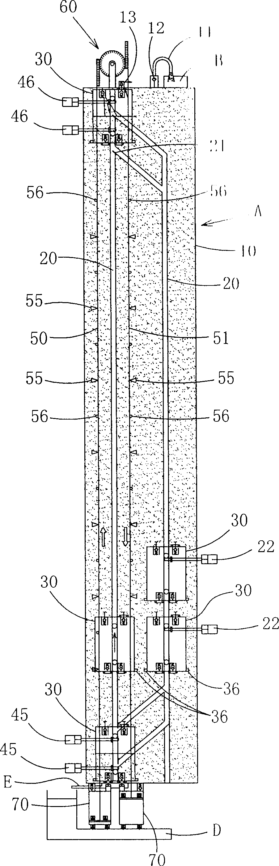
[0036] Such as Figure 1 to Figure 4 As shown, the present invention is a gravity-buoyancy cycle actuation hydroelectric power generation device, which is mainly provided with a gravity-buoyancy cycle operation to draw water to a high place, and the water-absorption tower A includes:

[0037] An airtight container 10, which has a certain height and is filled with water, the top of which is provided with an overflow pipe 11 having a check valve 12 and an exhaust check valve 13;

[0038] A guide rail 20, which is assembled in the airtight container 10, provides guidance and circulation for the buoy 30 to float and sink in the airtight container 10, wherein the intersection of the guide rail 20 in the lift and sink section can be provided with directions and segments Guided diverter 2...


PUM


Abstract

The hydraulic power plant driven by gravity and buoyancy circulation uses gravity and buoyancy circulation to draw the water to the water tower located at a high position. The water tower is an airtight container, which is installed with a slideway inside, and provided with one or more buoy inside for guidance and circulation of float and sink. The transmission rod, is affixed to the vertical slide stand inside the airtight container, so the buoys could drive and release transmission rods of the connectors during the float process, and the kinetic energy could be converted into mechanic energy. Sets of transmission rod drives a group of lift pumps by coordinating with the reverse linking device and repeated synchronization, so that the water tower becomes a pressure conductor and supplies water to the overflow pipe. The water tower provides high efficiency and power generation capacity with height-based water reservoir.

Description

technical field [0001] The present invention relates to a hydroelectric power generation device with gravity buoyancy cycle operation, in particular to a kind of cycle that utilizes a buoy to fill a closed container with gas and has buoyancy to lift, and utilizes the cycle in which the buoy to fill with water to have sinking gravity. Kinetic energy is converted into mechanical energy, so that several pumping pumps are repeatedly and synchronously driven to continuously supply water to the airtight container, so that the water pumping tower filled with water inside forms a pressure conductor (Pasquiau principle), and conducts the continuously supplied water. The overflow pipe with a check valve at the top flows out, that is, the water-drawing tower formed by the gravity buoyancy circulation, so that the water-drawing tower has the practical effect of self-sustaining high water storage and the innovative design of power generation benefits. Background technique [0002] At pre...

Claims


Application Information

Patent Timeline
Patent Type & Authority Applications(China)
IPC IPC(8): F03B17/04
CPCY02E10/20F03B17/04F03B17/02
Inventor 陈添泉
Owner 陈添泉
Why Eureka
Try Eureka