


Quick Research
Generate reliable direction feasibility study reports for your R&D in just a few steps.

Technical Q&A
Discover and master advanced knowledge NOW. Basics, ideas, possibilities, all at once.

Find Solutions
As an expert in R&D theories, this can generate solutions to your technical problems instantly.

Evaluate Feasibility
Analyze your overall solution with one click, know your potential R&D risks in advance.

Monitor Landscape
Get weekly tech updates, stay abreast of the latest tech innovations and key insights.
Anti-theft master device for lock
An anti-theft lock cylinder and lock cylinder technology, which is applied in building locks, cylinder pin locks, locks with turning keys, etc., can solve problems such as poor anti-theft function, and achieve the ideal effect of improving safety performance and anti-theft function.
- Summary
- Abstract
- Description
- Claims
- Application Information
AI Technical Summary
Problems solved by technology
Method used
Image

Examples
Embodiment Construction
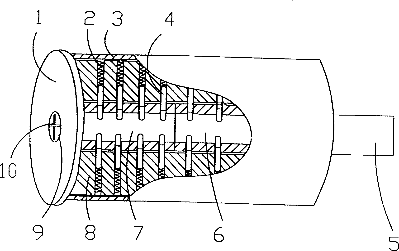
[0014] Concrete structure of the present invention can refer to figure 1 , figure 1 Reflected in is a structural diagram of an embodiment of a lock cylinder. The lock core housing 8 is axially provided with a mounting hole for inserting the rotating lock core, and the rotating lock core is movably inserted therein. The main rotating lock cylinder 6 is connected with the unlocked twist piece 5, the rear end of the auxiliary rotating lock cylinder 7 is adjacent to the front end of the main rotating lock cylinder 6, the front end of the auxiliary rotating lock cylinder 7 is in contact with the front end cover 1, and the key of the front end cover 1 Hole 9 is corresponding, and the effect of overcoat 3 is the torsion plate 5 of positioning rotating lock core 6,7 and unblanking. The pins 4 (two sections) are radially symmetrically arranged in four groups in the corresponding holes of the lock core housing 8 and the rotating lock core 6, 7, so as to adapt to the needs of the cross...
PUM
 Abstract
Description
Claims
Application Information
 - R&D Engineer
- R&D Manager
- IP Professional
- Industry Leading Data Capabilities
- Powerful AI technology
- Patent DNA Extraction
Browse by: Latest US Patents, China's latest patents, Technical Efficacy Thesaurus, Application Domain, Technology Topic, Popular Technical Reports.
© 2024 PatSnap. All rights reserved.Legal|Privacy policy|Modern Slavery Act Transparency Statement|Sitemap|About US| Contact US: help@patsnap.com