Ceramic brick feeding device and its use method

A technology for distributing devices and ceramic tiles, which is applied in the direction of supply devices, manufacturing tools, etc., can solve the problems of long displacement distance of grid 1, large displacement deformation of powder material, large pattern deformation, etc., and achieve small relative displacement deformation and accurate distribution , the effect of small displacement deformation

Inactive Publication Date: 2006-11-29
KEDA INDUSTRIAL GROUP CO LTD
View PDF0 Cites 5 Cited by
  • Summary
  • Abstract
  • Description
  • Claims
  • Application Information

AI Technical Summary

Problems solved by technology

In this process, the grid 1 is in contact with the platform 3, the mold frame 4 and the mold core 5 successively, so the displacement distance of the grid 1 is long, and the displacement friction distance of the bottom surface of the powder in the grid 1 is also long, and the grid 1 is relatively long. The moving distance of the powder 2 is also long, which eventually leads to a large displacement and deformation of the powder in the grid 1, and the phenomenon of powder tumbling is serious, such as Figure 2A The situation shown
Figure 1B It is a schematic diagram of the powder pattern after ordinary grid filling, Figure 2B It is a schematic diagram of the powder pattern after the ordinary grid cloth is put into the mold frame. It can be seen from the figure that the pattern deformation is large

Method used


Image

  • Ceramic brick feeding device and its use method
  • Ceramic brick feeding device and its use method
  • Ceramic brick feeding device and its use method

Examples


Embodiment Construction

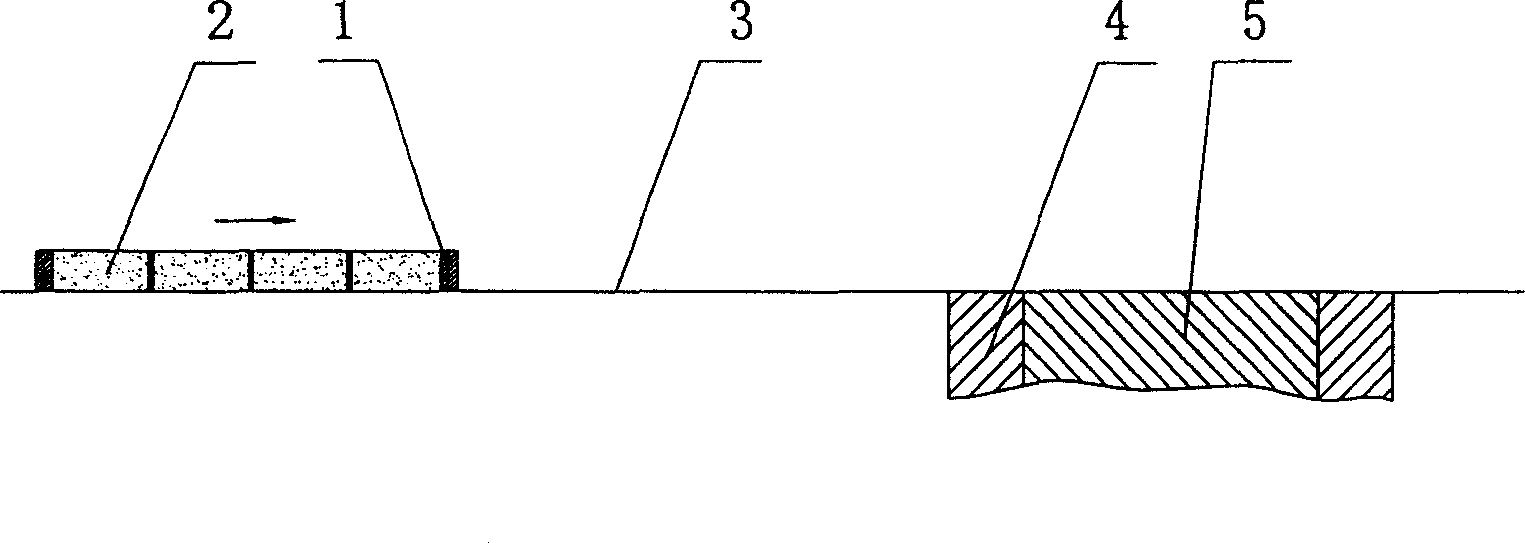
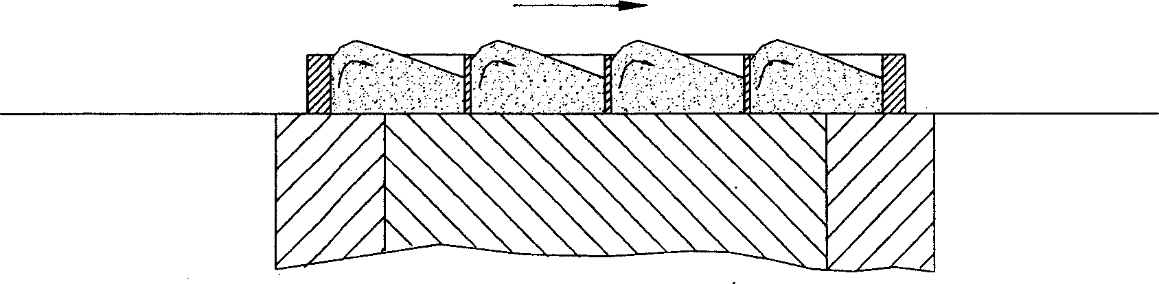
[0041] image 3 It is a structural schematic diagram of an embodiment of the single-layer movable floor distribution device of the present invention. The device of the present invention comprises a grid 1, and a movable bottom plate 8 which can make the ceramic brick powder 2 in the grid fall by moving is arranged under the grid 1. Such as image 3 As shown, since the movable bottom plate 8 is added under the grid 1, the bottom surface of the powder material 2 is directly in contact with the movable bottom plate 8. When the device of the present invention is transferred to the mold frame 4, since the movable bottom plate 8 has no displacement relative to the powder material , so there is no powder displacement deformation, only when the device of the present invention is moved to the plane of the mold core 5, the movable bottom plate 8 has a relative displacement process with respect to the powder 2, and the displacement distance is relatively short. Compared with the prior ...


PUM


Abstract

A raw material distributing apparatus for producing ceramic tile is composed of a grate, a movable bottom plate under said grate, and a bottom grate under said movable grate. Its application includes such steps as filling the raw powder of ceramic tile in said grate, moving it to a position on a core mould, removing bottom plate to drop the raw powder in the core mould, dropping the core mould in a frame mould, removing said distributing apparatus, and leveling the surface of raw material in the frame mould.

Description

technical field [0001] The invention relates to a ceramic brick distributing device and a use method thereof, which can reduce the displacement and deformation of powder during the ceramic brick distributing process, realize precise distributing and save resources. Background technique [0002] Such as Figure 1A As shown, the distribution of the existing ceramic tiles is mainly by filling the grid placed on the platform, and then pushing the filled grid to the mold frame of the press through the platform surface, and the lower mold core sinks. The powder in the grid enters the mold cavity, and the grid moves backwards, covering and leveling the powder falling into the mold cavity, returning to the initial filling position, and completing a working cycle of a distributing process (filling, feeding, distributing) . [0003] However, during the movement of the grid, due to the friction between the powder in the grid and the platform surface, and the movement of the grid relat...

Claims


Application Information

Patent Timeline
Patent Type & Authority Applications(China)
IPC IPC(8): B28B13/02
Inventor 刘湘晖
Owner KEDA INDUSTRIAL GROUP CO LTD
Why Eureka
Try Eureka