Push belt

A technology of pulleys and components, which is applied in the belt pressure field of continuously variable transmissions, can solve problems such as consumption and torque reduction, and achieve the effects of torque transmission, deflection prevention, and high-efficiency torque transmission

Active Publication Date: 2006-11-22
ROBERT BOSCH GMBH
View PDF5 Cites 7 Cited by
  • Summary
  • Abstract
  • Description
  • Claims
  • Application Information

AI Technical Summary

Problems solved by technology

It is evident that in this skewed orientation part of the clamping force exerted by the pulley sheaves on each side of the element lying in said curved trajectory line is dissipated, and thus, by means of friction in the variator The torque transferable between the pulleys is significantly less than desired

Method used


Image

  • Push belt
  • Push belt
  • Push belt

Examples


Embodiment Construction

[0019] In the figures, the same reference numerals correspond to the same or at least comparable technical features.

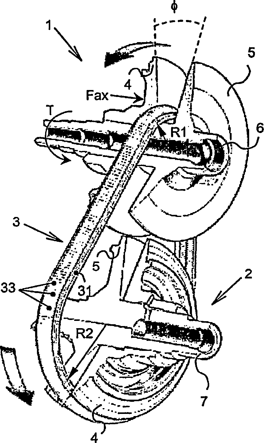
[0020] figure 1 The central part of a known continuously variable transmission is shown, which is usually applied on the drive train of a family car, between the engine and the drive wheels. The variator comprises two pulleys 1, 2 provided respectively with two pulley sheaves 4, 5 between which a metal pressure belt 3 is arranged for transferring the rotational movement from one pulley 1 and the associated The torque is transmitted to the other pulley 2. The pulley sheaves 4 , 5 are substantially conically shaped and at least one pulley sheave 4 is accommodated in the transmission in such a manner that it is axially displaceable along a carried corresponding pulley shaft 6 , 7 . The variator usually also comprises actuating means, which exert an axially directed clamping force Fax on said at least one pulley 4, directed towards the corresponding other pulley...


PUM


Abstract

The invention relates to a push belt (3) for a continuously variable transmission where the belt (3) is partly clamed between sheaves (4, 5) of a pulley (1, 2) of the transmission that comprises an endless tensile means (31) and a multitude of platelike transverse elements (33) that are provided on the tensile means (31) oriented predominantly transversely thereto and movable along its longitudinal direction, which elements (33) each show locking means (39, 40; 50, 51) for limiting a relative movement in either transverse or axial direction between two adjacent elements (33), i.e. an axial play DX, which is at most equal to the square of the element's dimension in the longitudinal direction Tact divided by the element's dimension in the axial direction Wact.

Description

technical field [0001] The present invention relates to a push belt of a continuously variable transmission, and more particularly to a push belt for a motor vehicle as defined in the preamble of claim 1 . Background technique [0002] Such tapes are well known in the art, more specifically from the applicant's Dutch patent application NL-1022022 and from the applicant's European patent applications EP-A-0329206 and EP-A-0626526. known, of which Dutch patent application NL-1022022 is incorporated herein by reference and which was not published before the filing date of the present application. Said Dutch patent application discloses the desire to achieve a belt design which avoids the use of bumps and notches (holes) provided in conventional techniques. [0003] Such a generally provided, mutually matching projection and recess is known, for example, from European patent application EP-A-0329206, in which document the projection is shaped conically. In most cases, however,...

Claims


Application Information

Patent Timeline
Patent Type & Authority Applications(China)
IPC IPC(8): F16G5/16
CPCF16G5/16F16H9/24
Inventor 科内利斯·约翰内斯·马里亚·范德梅尔罗伯特·阿诺尔德斯·安德烈亚斯·穆特塞尔斯卢卡斯·亨德里克斯·罗伯图斯·马里亚·普林森
Owner ROBERT BOSCH GMBH
Why Eureka
Try Eureka