Work transfer device for press machines

一种输送装置、工件的技术,应用在进给装置、定位装置、储存装置等方向,能够解决机器人障碍、作业复杂、缩短等问题,达到高精度的定位、高速输送定位、设置空间小的效果

Inactive Publication Date: 2006-11-15
KOMATSU LTD
View PDF3 Cites 10 Cited by
  • Summary
  • Abstract
  • Description
  • Claims
  • Application Information

AI Technical Summary

Problems solved by technology

[0016] However, in such Figure 17 In the conventional conveying press shown, the feed box with the feed drive unit 115 built in is installed on the side of the press main body, and the lift box with the lift drive unit 117 built in is provided between the left and right support rods 121. Alternatively, the clamp box with the clamp drive unit 116 built in complicates the structure of the drive mechanism and becomes a factor leading to an increase in manufacturing cost.
[0017] Also, because the feed box in which the feed drive unit 115 is built protrudes greatly from the side of the press main body to the outside, it has the following problems: it becomes an obstacle when a material supply device or a robot for workpiece output is installed, and as a pressure The shape of the machine requires a wide installation space
Therefore, there is a problem that the work at the time of mold replacement is complicated, and the time for mold replacement cannot be shortened.

Method used


Image

  • Work transfer device for press machines
  • Work transfer device for press machines
  • Work transfer device for press machines

Examples


no. 1 approach

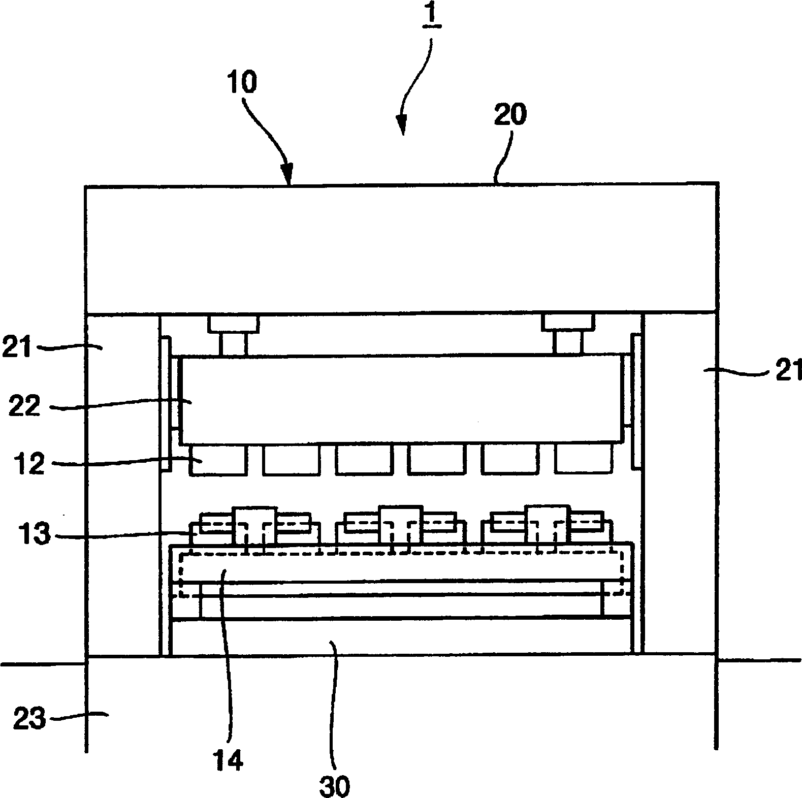
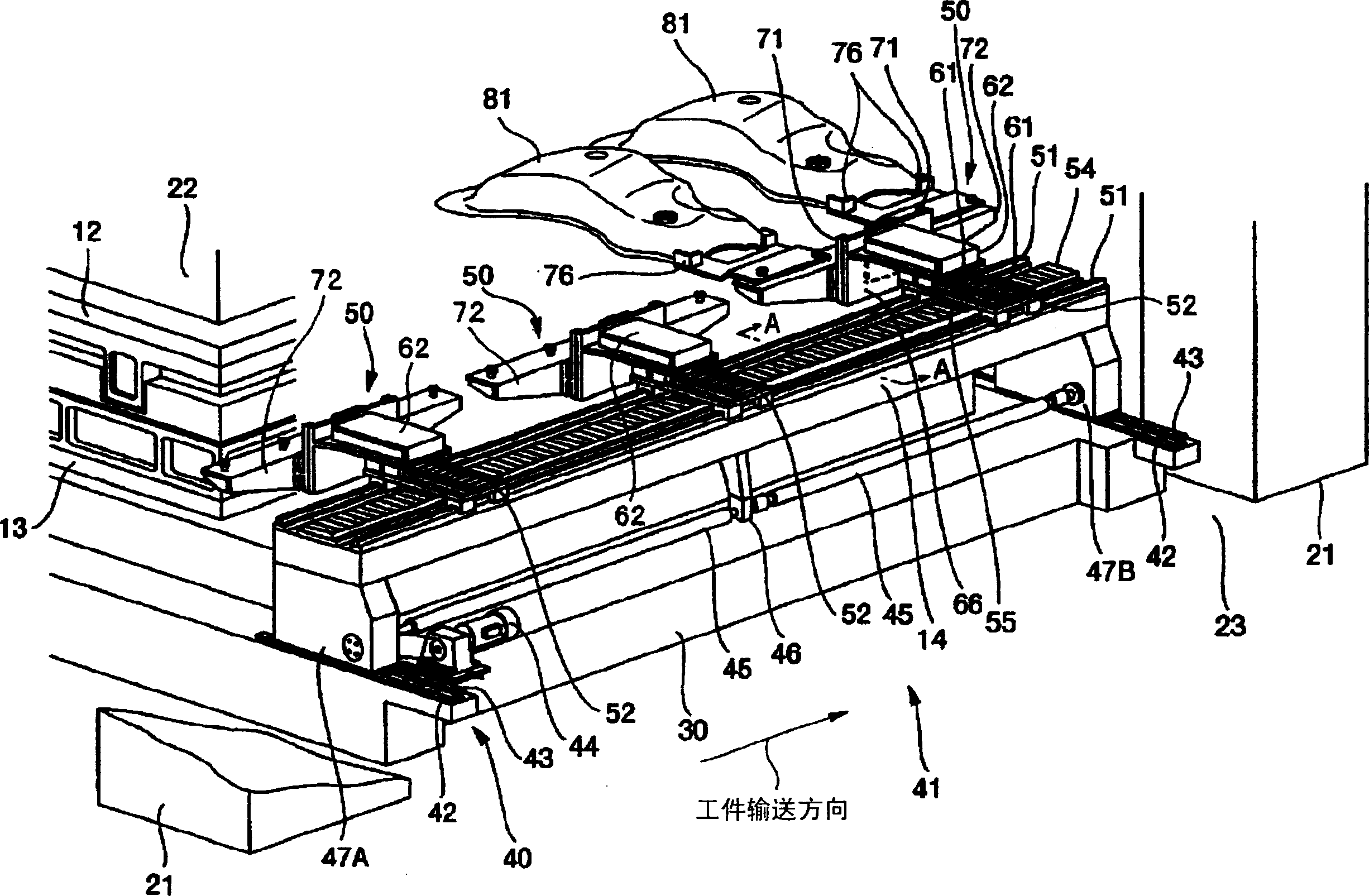
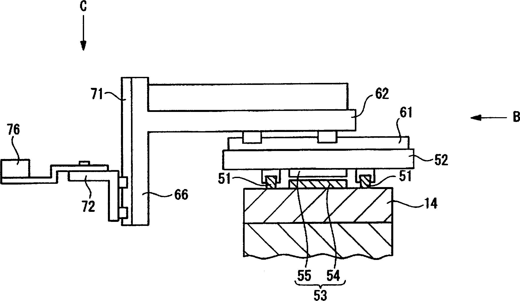
[0092] figure 1 It is a front view of the conveying and feeding device (press machine) 1 provided with the workpiece conveying device according to the first embodiment of the present invention. figure 2 It is a perspective view of the conveying and feeding device 41 which is a workpiece conveying device. Figure 3 to Figure 5 An enlarged view of a part of the transport feeding device 41 is shown.

[0093] First, if figure 1 As shown, four pillar-shaped struts 21 are erected on the machine base 23 located at the bottom of the press frame 10 of the conveying press 1 , and a beam 20 is arranged on the upper surface of the struts 21 . A sliding drive device is built in the crossbeam 20 to lift and drive the slide plate 22 below the crossbeam 20 . Furthermore, the upper die 12 is attached to the lower surface of the slide plate 22 . An upper mold 13 is arranged on the upper surface of the movable backing plate 30 opposite to the slide plate 22 , and the workpiece is press-fo...

no. 2 approach

[0121] Next, use Figure 12 The conveying and feeding device 41A of the second embodiment will be described. Figure 12 It is a perspective view of the conveying and feeding device 41A which is a workpiece conveying device. The same reference numerals are attached to the same components as those described in the first embodiment, and description thereof will be omitted.

[0122] A lower mold 13 is provided on the upper surface of the movable backing plate 30A opposite to the slide plate 22 (refer to figure 2 ), using the upper mold 12 (refer to figure 2 ) and the linkage of the lower mold 13 to press-form the workpiece. A pair of left and right rods 14 , 14 extend parallel to the workpiece conveying direction with the upper die 12 and the lower die 13 interposed therebetween.

[0123] Figure 12 In the illustrated case only one side of the pair of rods 14A, 14A is shown. Such as Figure 12 As shown, on the movable backing plate 30A that can move automatically, in Fi...

no. 3 approach

[0136] Next, use Figure 13 The conveying and feeding device 41B of the third embodiment will be described. Figure 13 It is a perspective view of the conveying and feeding device 41B which is a workpiece conveying device. The same reference numerals are attached to the same components as those described in the first embodiment, and description thereof will be omitted.

[0137] In the third embodiment, in the first embodiment, adjacent feed pallets 52 are connected by a connection mechanism 56 . Thereby, the several feed pallet 52 is arrange|positioned so that the adjacent feed pallet 52 may respectively have predetermined intervals. By disposing in this way, all the feed pallets 52 supported by one rod 14 operate in conjunction with each other, so it is not necessary to provide a feed drive mechanism for each of the feed pallets 52 . exist Figure 13 Among them, only one feed pallet 52 on the upstream side is provided with a linear motor 53B which is a feed drive mechanism....


PUM


Abstract

A transfer feeder (41) for a transfer press (1) comprises a pair of bars (14) disposed on a moving bolster (30) in parallel with the direction of work transfer, a feed carrier (52) supported by the bars (14) and movable in the direction of work transfer, a clamp carrier (62) supported by the feed carrier (52) and movable in the direction of clamp, and a lift carrier (72) supported by the clamp carrier (62) and movable in the direction of lift. Since a large drive mechanism is unnecessary, simplification of the construction can be enhanced. Further, since the whole of a transfer feeder (41) is disposed on a moving bolster (30), the moving bolster (30) in its entirety can be carried out of the transfer press (1), thus facilitating mold change operation.

Description

technical field [0001] The invention relates to a workpiece conveying device for a press machine. Background technique [0002] Figure 17 Showing a conventional transfer press 100 as a press, four columnar struts 121 are erected on a base 123 located at the bottom of a press frame 110 , and a beam 120 is provided on the upper surface of the struts 121 . A sliding drive device is built in the crossbeam 120 to lift and drive the slide plate 122 below the crossbeam 120 . Furthermore, an upper die 112 is attached to the lower surface of the slide plate 122 . A lower mold 113 is provided on the upper surface of the movable backing plate 130 opposite to the sliding plate 122 , and the workpiece is press-formed by the linkage of the upper mold 112 and the lower mold 113 . A pair of left and right feed rods 114 and 114 are extended in parallel so as to sandwich the upper die 112 and the lower die 113 . A pair of feed rods 114, 114 is oppositely provided with a manipulator (not s...

Claims


Application Information

Patent Timeline
Patent Type & Authority Applications(China)
IPC IPC(8): B21D43/05B21D37/04B21D43/10
CPCB21D43/05B21D43/10
Inventor 城座和彦
Owner KOMATSU LTD
Why Eureka
Try Eureka