
Electromagnetic permanent magnet electric machine

A permanent magnet motor and electromagnetic technology, applied in the field of electric motors, can solve the problems of difficult excitation adjustment of permanent magnet motors, small air gap magnetic density, low efficiency of electric excitation motors, etc., to prevent irreversible demagnetization, excellent magnetic properties, and saving raw materials Effect

Inactive Publication Date: 2006-11-15
赵克中 +2
View PDF1 Cites 3 Cited by
  • Summary
  • Abstract
  • Description
  • Claims
  • Application Information

AI Technical Summary

Problems solved by technology

[0009] The invention provides a new type of electromagnetic permanent magnet motor, which can adjust the magnetic density of the air gap between the stator and the rotor, can overcome the difficulty in adjusting the excitation of the existing permanent magnet motor, and solve the problem of low efficiency of the existing electric excitation motor and the air gap problem. Less magnetic density

Method used


Image

  • Electromagnetic permanent magnet electric machine
  • Electromagnetic permanent magnet electric machine
  • Electromagnetic permanent magnet electric machine

Examples


Embodiment Construction

[0029] A detailed explanation and examples of the invention are provided below:

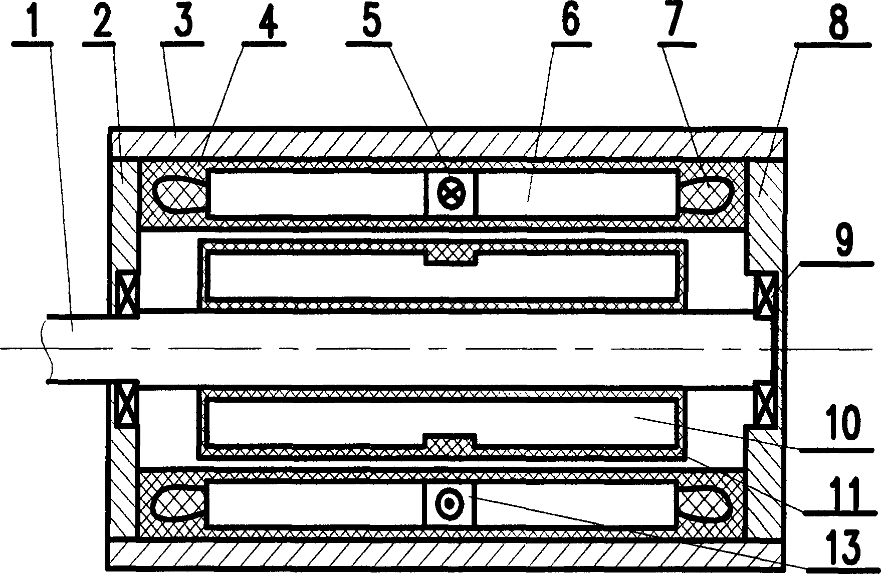
[0030] Basic structure of the present invention sees figure 1 , wherein the stator and the rotor are sealed with polymer materials, such as polymer resin materials, respectively.

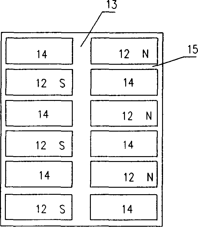
[0031] The arrangement of the permanent magnet and the magnetic adjustment pole on the rotor of the present invention is as follows: image 3 and shown in Figure 4. Depend on image 3As can be seen from FIG. 4 , an annular groove 13 is arranged on the rotor core 16 , and this annular groove is arranged at half of the rotor width. The excitation coil 7 is arranged on the stator corresponding to the annular groove 13 . Axial slots along the axial direction are arranged on both sides of the annular slot on the rotor, and these axial slots are arranged at staggered intervals along both sides of the annular slot. Between each axial slot is a magnetic adjustment pole 14 made of soft iron of the rotor core. The permanen...


PUM


Abstract

The invention relates to the electromotor, the stator iron core is mounted on the electromotor, the three phase symmetry winding is mounted on the stator iron core, the permanent magnet is fixed on the rotor iron core. The generator rotor of the invention is mounted with one loop slop locating on the half of the width. Two sides of the loop slop are mounted with the slop along the direction of the axis on the rotor, and these slops are collocated distantly along the sides of the loop slot, the slop along the axis is the adopting pole constructed by the rotor iron core soft iron. The permanent magnet are fixed on the slot along the axis, thereinto, each permanent magnet N poles located in the slot along the axis on the side of the loop slot point at the centre of the a circle of the rotor, and the S pole of each permanent magnets located on the other side of the loop slot point at the centre of the circle of the rotor, so the magnet direction formed is the magnetization along the axis.

Description

technical field [0001] The invention relates to a motor with a stator iron core, three-phase symmetrical windings on the stator iron core and permanent magnets fixed on the rotor iron core. Background technique [0002] The traditional three-phase AC motor is equipped with three-phase symmetrical windings on the stator core, and the rotor is a squirrel cage frame. The three-phase rotating magnetic field generated by the stator is used to generate the induced electromotive force on the rotor to generate follow-up rotation. This motor has a low power factor and poor drive characteristics. [0003] Since the magnetic energy product of permanent magnets, especially rare earth permanent magnets, is much higher than that of electromagnets, their magnetic energy density is close to the level of superconducting devices. Therefore, placing such permanent magnets in the rotor of an induction motor will result in a motor with high efficiency and power factor. Moreover, this motor can...

Claims


Application Information

Patent Timeline
Patent Type & Authority Applications(China)
IPC IPC(8): H02K21/12H02K1/27H02K21/14
Inventor 赵克中丁齐祺丁成斌
Owner 赵克中
Learn More