Device and method for continuously producing fluorescent tubes

A technology for fluorescent tubes and production equipment, applied in the manufacture of discharge tubes/lamps, machines with sequentially arranged working positions, electrical components, etc., can solve the problems of continuous production equipment for fluorescent tubes, unresolved problems of technical connection, manpower and Energy waste and other issues, to achieve the effect of increasing per capita productivity, reducing personnel, and saving energy

Inactive Publication Date: 2006-11-15
ZHEJIANG YANKON GROUP
View PDF0 Cites 13 Cited by
  • Summary
  • Abstract
  • Description
  • Claims
  • Application Information

AI Technical Summary

Problems solved by technology

[0002] The existing production process of fluorescent tubes mainly includes processes such as bending, powder coating, tube baking, sealing, bridging, exhausting and seasoning. At present, in the whole processing process, multiple devices in the same process are concentrated to produce the same tube. For semi-finished products, each process is independent of each other, which not only causes a lot of waste of manpower and energy, but also has a very low production efficiency. If the existing processing equipment is connected in series, the problem of technical connection cannot be solved. Also need to carry out a large amount of manual operations, so far, still do not have the continuous production device of fluorescent tube on the true sense

Method used


Image

  • Device and method for continuously producing fluorescent tubes
  • Device and method for continuously producing fluorescent tubes
  • Device and method for continuously producing fluorescent tubes

Examples


Embodiment 1

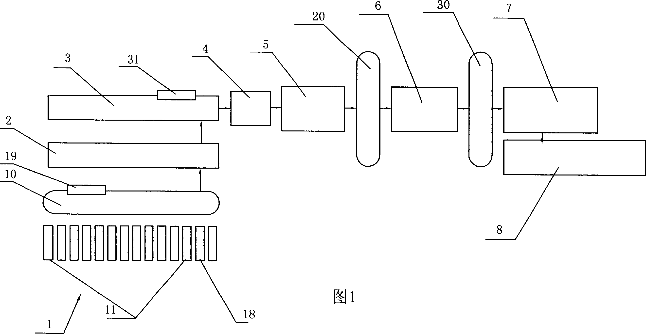
[0023] Embodiment 1: A continuous production device for fluorescent tubes, including a pipe bending device 1, a film coating device 2, a powder coating device 3, a tube baking device 4, a sealing device 5, a bridging device 6, an exhaust device 7 and an aging device 8. The pipe bending device 1 is provided with twelve pipe bending mechanisms 11 in parallel. The pipe bending mechanism 11 includes a heating channel 12 and a pipe bending fixture (not shown). The heating channel 12 is provided with a glass tube inlet 13 and a glass tube outlet 14. The heating A lower burner 15 and an upper burner 16 are arranged in the channel 12 close to the glass tube outlet 14, a hot gas outlet 17 is set in the upper end of the heating channel 12 close to the glass tube inlet 13, and the powder coating device 3 is provided with an automatic coil The powder device 31, the baking tube device 4 is an oven 41 with an upper seal, the inlet 42 and the outlet 43 of the oven 41 are arranged at the botto...

Embodiment 2

[0024] Embodiment 2: Other structures are the same as Embodiment 1, the difference is that the pipe bending device 1 is provided with twelve pipe bending mechanisms 11 and two spare pipe bending mechanisms 18 in parallel, and the sealing device 5 is provided with twelve parallel and synchronous operation The sealing fixture 51, the bridging device 6 is provided with twelve tooling fixtures 61 running side by side and synchronously, the spare pipe bending mechanism 18 has the same structure as the pipe bending mechanism 11, and an automatic Switching mechanism (not shown), when the bending mechanism 11 breaks down, the pipe bending mechanism 11 can be replaced by a spare bending mechanism 18 through an automatic switching mechanism.

Embodiment 3

[0025] Embodiment 3: Other structures are the same as Embodiment 2, except that the hot air outlet 17 is provided with a hot air pipe (not shown) communicating with the film coating device 2 and the powder coating device 3 .


PUM


Abstract

This invention discloses fluorescent lamp tube continuous generating device, it includes swan neck device, swab, dusting device, baking device, sealing device, bridge connecting device, exhaust device and tact device. The features are that at least two swan neck mechanisms parallel set on the swan neck device, and at least two parallel synchronous operational sealing clampers and compaction film corresponding to the clamper on the sealing device. At least two parallel synchronous operational frock clampers are set on the bridge connecting device. At least two groups of exhausting mechanisms set on the exhausting device, at least two exhausting service positions are set on the exhausting device. Compositor are set between the swan neck device and the swab, the sealing device and the bridge connecting device, bridge connecting device and exhausting device. Manipulators are set between each device. The advantages are that three compositors are used to realize ordered connecting between each separate device, it is the real fluorescent lamp continuous generating device, the generating efficiency can be greatly improved and human power can be reduced.

Description

technical field [0001] The invention relates to a production device for fluorescent lamps, in particular to a continuous production device and production method for fluorescent lamp tubes. Background technique [0002] The existing production process of fluorescent tubes mainly includes processes such as bending, powder coating, tube baking, sealing, bridging, exhausting and seasoning. At present, in the whole processing process, multiple devices in the same process are concentrated to produce the same tube. For semi-finished products, each process is independent of each other, which not only causes a lot of waste of manpower and energy, but also has a very low production efficiency. If the existing processing equipment is connected in series, the problem of technical connection cannot be solved. Also need to carry out a large amount of manual operations, up to now, still do not have the continuous production device of fluorescent tube in the real sense. Contents of the in...

Claims


Application Information

Patent Timeline
IPC IPC(8): H01J9/00H01J9/46
Inventor 陈卫茅建龙
Owner ZHEJIANG YANKON GROUP
Why Eureka
Try Eureka