
Motor stator

A technology for electric motors and stators, which is applied in the direction of electric components, electromechanical devices, electrical components, etc., and can solve the problems of reduced workability of winding settings, longer winding length, and power line contact, etc.

Active Publication Date: 2006-11-08
DAIKIN IND LTD
View PDF1 Cites 8 Cited by
  • Summary
  • Abstract
  • Description
  • Claims
  • Application Information

AI Technical Summary

Problems solved by technology

[0004] However, for example, in a stator with six-slot concentrated winding, the same phase is located at opposite positions by 180 degrees, so the lead-in length of the winding becomes longer when wiring, which reduces the workability of winding installation.
Also, there is a possibility that the power line comes into contact with the tooth windings of other phases

Method used


Image

  • Motor stator
  • Motor stator
  • Motor stator

Examples


Embodiment Construction

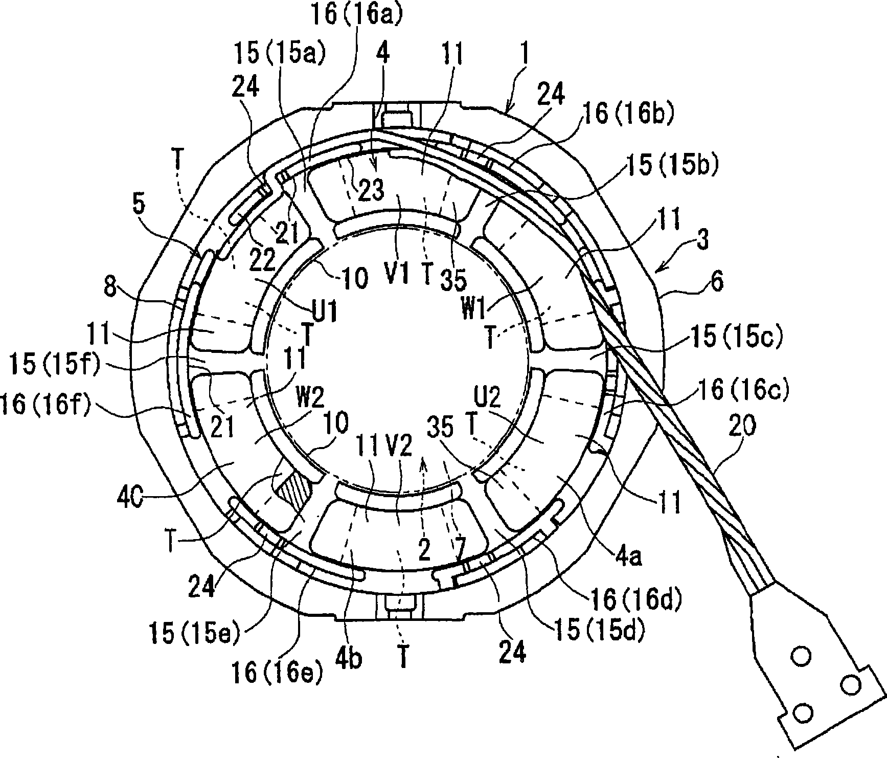
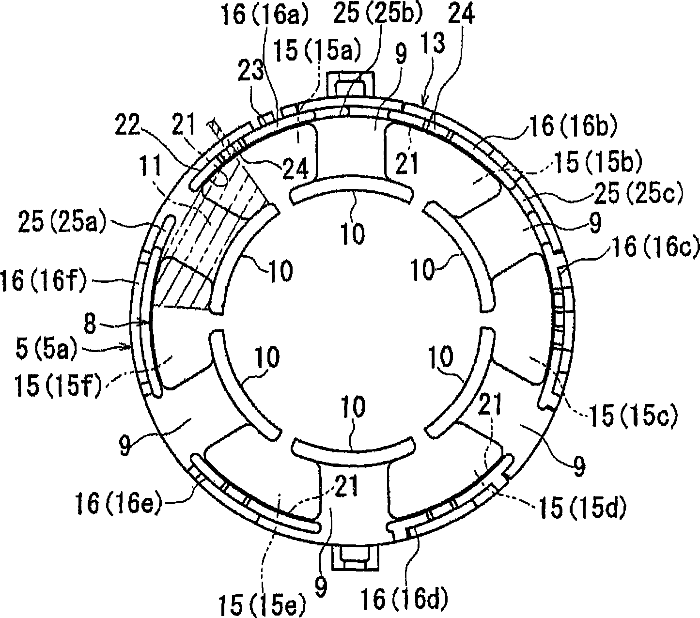
[0015] Hereinafter, specific embodiments of the stator of the motor according to the present invention will be described in detail with reference to the drawings. figure 1 It is a schematic diagram of the main part of the electric motor using this stator. The stator 1, the rotor 2 rotatably embedded in the stator 1, and the like constitute a motor. The stator 1 includes a stator core 3 and a winding 4 wound around the stator core 3 . In addition, the stator core 3 includes: a core body 6 formed by laminating a plurality of annular thin plates made of electromagnetic steel sheets; , 5 (refer to Figure 1 to Figure 3 ). In addition, a plurality of (six in this case) teeth T, . At this time, grooves 15, . . . are formed between adjacent teeth T, T in the circumferential direction. In addition, in this case, there are six grooves 15, that is, the first groove 15a to the sixth groove 15f.

[0016] In addition, the rotor 2 has a rotor core 7 and a plurality of magnets (not sho...


PUM


Abstract

An electric motor stator having windings (4) installed therein in such a manner that winding of each winding (4) is started from a neutral wire around one of opposed teeth (T), a crossover wire to the other teeth (T) is extended so as to be a power wire, and winding is restarted from the power wire around the other teeth (T), and the terminal end of the winding for the other teeth (T) is drawn out to the neutral wire and connected to it. A stator core (3) is provided with an insulator (5) having support portions (16) for preventing tooth winding portions (11) from falling outwards. The power wire is held between the tooth winding portion (11) and a slot bottom (21) so as to be fixed.

Description

technical field [0001] The invention relates to a stator of an electric motor. Background technique [0002] The electric motor has a stator and a rotor rotatably arranged in the stator. In addition, conventionally, a stator includes a stator core having a plurality of teeth, and a coil wound around the teeth of the stator core. Such an electric motor is used, for example, as an electric motor for a compressor of an air conditioner. [0003] Incidentally, although the winding is wound around each tooth, it is necessary to use an insulating tube, an insulating sheath, or the like for the winding for insulation at this time. Therefore, in the past, there is such a technology: a slot is provided on the insulator of the stator core, and the connection wire of the winding is accommodated in the slot to prevent contact with other phases, thereby realizing the omission of insulating tubes and the like (for example, refer to Japan Patent Publication JP-A-2002-101596). [0004] H...

Claims


Application Information

Patent Timeline
Patent Type & Authority Applications(China)
IPC IPC(8): H02K3/18H02K3/28H02K3/52
CPCH02K3/28H02K3/522H02K3/47H02K7/083
Inventor 天野龙一郎
Owner DAIKIN IND LTD
Learn More