


Quick Research
Generate reliable direction feasibility study reports for your R&D in just a few steps.

Technical Q&A
Discover and master advanced knowledge NOW. Basics, ideas, possibilities, all at once.

Find Solutions
As an expert in R&D theories, this can generate solutions to your technical problems instantly.

Evaluate Feasibility
Analyze your overall solution with one click, know your potential R&D risks in advance.

Monitor Landscape
Get weekly tech updates, stay abreast of the latest tech innovations and key insights.
Voltage check device
A technology of voltage detection and voltage, which is applied in the direction of measuring device, switchgear, switchgear setting, etc., can solve the problems of insulation damage and insulation resistance reduction, and achieve the effect of reliable suppression measures and prevention of insulation resistance reduction
- Summary
- Abstract
- Description
- Claims
- Application Information
AI Technical Summary
Problems solved by technology
Method used
Image

Examples
Embodiment approach 1
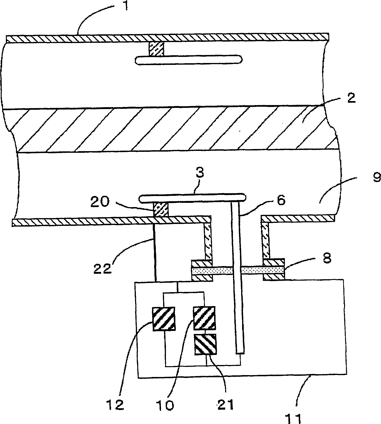
[0038] Hereinafter, a voltage detection device for gas-insulated equipment according to Embodiment 1 of the present invention will be described. figure 1 It is a schematic configuration diagram of the voltage detection device according to Embodiment 1 of the present invention.
[0039] The grounded metal container 1, which is a conductive container composed of conductive members, is filled with an insulating gas such as SF6 gas in a cylindrical casing constituting a gas insulated device such as a gas insulated switch.
[0040] A bus bar 2 , which is a high-voltage conductor to be detected, is arranged coaxially inside the grounded metal container 1 . The cylindrical intermediate electrode and the grounded metal container 1 are arranged coaxially between the grounded metal container 1 and the bus bar 2, and the grounded metal container 1 and the bus bar 2 are electrically insulated and installed. The intermediate electrode 3 is insulated and supported on the inner surface of ...
Embodiment approach 2
[0097] In the voltage detection device of the first embodiment described above, the resistor 21 is provided in the outer case 11 that accommodates the second capacitor 10 and the voltage sensor 12, but the configuration of the voltage detection device may also be as follows: Figure 10 . shown. That is, the resistor 21 can be inserted into the middle of the ground wire 22 connecting the outer box 11 and the grounded metal container 1 to be inserted into the conductive path leading to the grounded metal container 1 from the low voltage side of the second capacitor 10 . In addition, a lead wire 30 for grounding that is electrically connected to the outer case 11 and the ground line is provided. the rest of the composition and figure 1 The voltage detection device shown is the same.
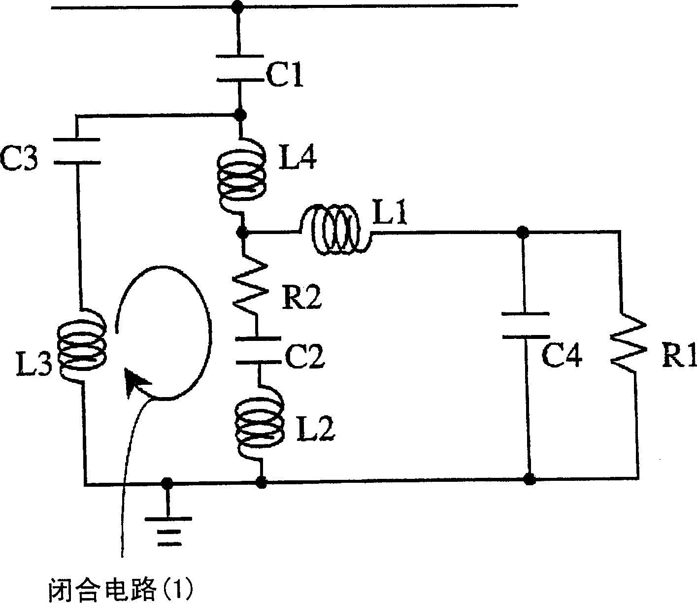
[0098] Figure 11 express Figure 10 The equivalent circuit diagram of the voltage detection device is shown. Figure 11 C1~C4, L1~L4, R1, and R2 in the above-mentioned embodiment 1 figure ...
Embodiment approach 3
[0114] Hereinafter, the resistance value of the resonance suppressing resistor 21 used in the first and second embodiments described above will be described.
[0115] Generally, when the resistance value R is large, Q indicating the sensitivity of resonance occurring in a closed circuit can be expressed by the following equation.
[0116] Q=1 / R×√(L / C) …(6)
[0117] combine figure 2 The equivalent circuit becomes
[0118] L=L2+L3+L4, C=1 / (1 / C2+1 / C3), R=R2...(7)
[0119] Since the larger the Q, the larger the resonance, so the larger the resistance value of the resistor 21, the more the resonance in the closed circuit (1) can be suppressed.
[0120] However, if using figure 2 As described above, the voltage sharing ratio (voltage division ratio) is determined by the ratio of the impedance of C1 in the voltage detection device to the total impedance of the low-voltage side of C1. The larger the resistance value of the resistor 21, the better the effect of suppressing reson...
PUM
 Abstract
Description
Claims
Application Information
 - R&D Engineer
- R&D Manager
- IP Professional
- Industry Leading Data Capabilities
- Powerful AI technology
- Patent DNA Extraction
Browse by: Latest US Patents, China's latest patents, Technical Efficacy Thesaurus, Application Domain, Technology Topic, Popular Technical Reports.
© 2024 PatSnap. All rights reserved.Legal|Privacy policy|Modern Slavery Act Transparency Statement|Sitemap|About US| Contact US: help@patsnap.com