Vibrating device for jet flow generating including a voice coil motor

A technology of vibrating device and vibrating piece, applied in electromechanical devices, circuits, electrical components, etc., can solve the problems of bending of the vibrating piece, loud noise, and the vibration will not transmit gas effectively, and achieve the effect of suppressing noise and increasing rigidity

Inactive Publication Date: 2006-11-01
SONY CORP
View PDF3 Cites 3 Cited by
  • Summary
  • Abstract
  • Description
  • Claims
  • Application Information

AI Technical Summary

Problems solved by technology

However, if the amplitude is increased too much, the vibrating plate will bend and the vibration will not be effectively transmitted to the gas
As a result, extremely noisy

Method used


Image

  • Vibrating device for jet flow generating including a voice coil motor
  • Vibrating device for jet flow generating including a voice coil motor
  • Vibrating device for jet flow generating including a voice coil motor

Examples


Embodiment

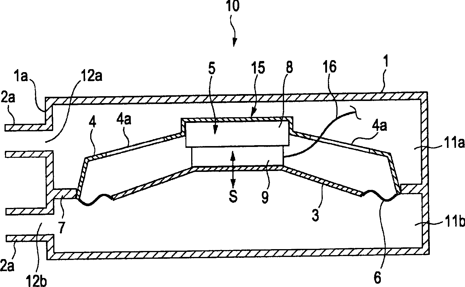
[0065] figure 1 is a perspective view of the jet flow generating device according to the first embodiment of the present invention. figure 2 for figure 1 A cross-sectional view of the jet flow generating device shown.

[0066] The jet flow generating device 10 includes a casing 1 with a circular rear part and a vibrating device 15 arranged inside the casing 1 . On the front face 1a of the cabinet 1, a plurality of rows of nozzles 2a and 2b are provided. Such as figure 2 As shown, the interior of the casing 1 is divided into an upper chamber 11a and a lower chamber 11b by the connecting piece 7 connecting the vibrating device 15 . Openings 12a and 12b are formed at positions corresponding to the nozzles 2a and 2b on the front surface 1a of the cabinet 1 where the nozzles 2a and 2b are provided, respectively. In this way, the upper chamber 11 a and the lower chamber 11 b communicate with the outside of the cabinet 1 . The upper chamber 11a and the lower chamber 11b have ...


PUM


Abstract

A vibrating device configured to vibrate a gas inside a chassis to discharge the gas in a pulsating flow through an opening formed in the chassis includes a frame, a vibrating plate, a supporting member that is attached to the frame and that is configured to support the vibrating plate in a manner such that the vibrating plate is vibratable, and a driving mechanism that is configured to drive the vibrating plate and that includes a magnetic circuit member attached to the frame and a voice coil body attached to the vibrating plate. The voice coil body is configured to prevent the voice coil body from contacting the magnetic circuit member when the vibrating plate is vibrating and is movable by means of a magnetic field generated by the magnetic circuit member.

Description

technical field [0001] The present invention relates to a vibrating device configured to apply vibration to gas to generate a gas jet, and more particularly, to a jet generating device including the vibrating device and an electronic device including the jet generating device. Background technique [0002] A known problem is that as the performance of personal computers (PCs) increases, the amount of heat dissipated from heat generating bodies such as integrated circuits (ICs) increases. Various heat dissipation technologies have been proposed, and products employing these technologies have been produced. As a method of dissipating heat, a heat sink made of metal such as aluminum is placed in contact with the IC so that heat is transferred from the IC to the heat sink. As another heat dissipation method, for example, a fan may be used to introduce low-temperature air into the surroundings of the heating element, and forcibly discharge the hot air in the PC casing to dissipa...

Claims


Application Information

Patent Timeline
Patent Type & Authority Applications(China)
IPC IPC(8): G06F1/20H01L23/467
CPCH02K33/18G06F1/00G06F1/20H01L23/467
Inventor 石川博一
Owner SONY CORP
Why Eureka
Try Eureka