
Horn pump

A horn and fluid technology, used in pumps, pumps with flexible working elements, liquid variable capacity machines, etc., can solve the problems of complex pump structure, monotonous form, lack of interest, etc.

Inactive Publication Date: 2006-10-04
王海金
View PDF0 Cites 0 Cited by
  • Summary
  • Abstract
  • Description
  • Claims
  • Application Information

AI Technical Summary

Problems solved by technology

Such a pump has a complex structure, but its form is relatively monotonous. In a modern society that pays attention to artistic atmosphere and diversification, it seems a bit lacking in interest.

Method used


Image

  • Horn pump

Examples


Embodiment Construction

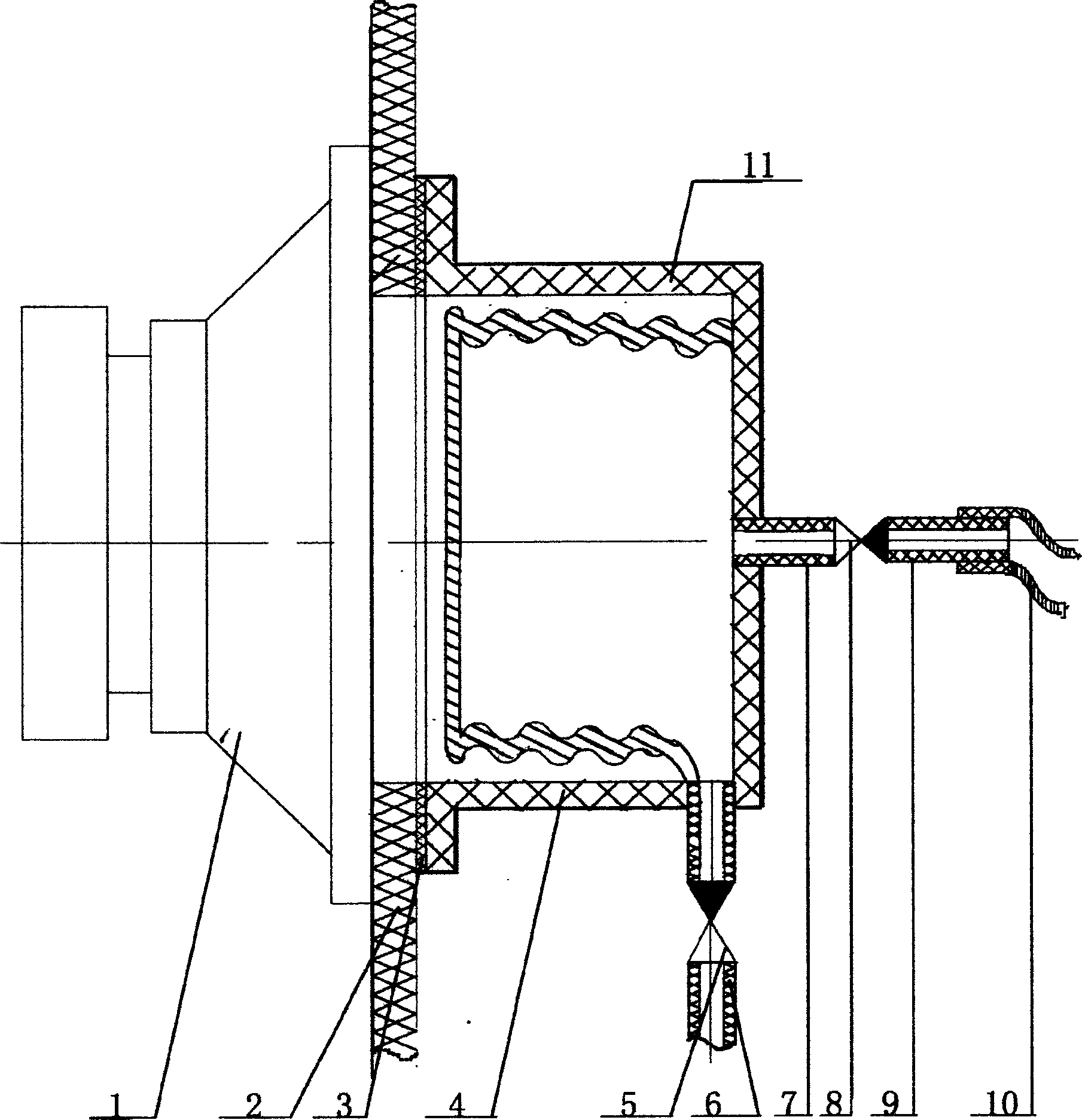
[0007] As can be seen from the accompanying drawings, the horn pump includes a horn 1, a speaker panel 2 for fixing the horn, and a fluid cover 4 is fixed on the speaker panel 2 at the outlet of the horn 1, and the cover 4 is provided with a fluid inlet and a fluid inlet for entering the fluid. The fluid outlet hole for going out, the fluid inlet hole is connected with the fluid inlet pipe 6, and the fluid inlet check valve 5 is connected on the inlet pipe 6, and the fluid inlet check valve is communicated with the inner chamber of the expandable liquid holding bag 11, and is connected with the bag. 11 The connected fluid outlet is connected with a fluid outlet pipe 7, and the fluid outlet pipe 7 is connected with an outlet check valve 8, and the cover 4 and the speaker panel 2 are sealed with a sealing gasket 3, and the outlet fluid check valve 8 can be installed There is a fluid pipe joint 9, and the fluid pipe joint 9 is connected with a fluid hose 10, and the fluid hose 10 ...


PUM


Abstract

The invention discloses a horn mercury, which comprises the following parts: horn, sound box bread board for fixing the horn, wherein one fluid cover is installed on the sound box bread board which is fixed at the exit of the horn; there are ingress fluid hole and outlet fluid hole on the cover for entering fluid and issuing the fluid; the ingress fluid hole connects to the outlet fluid hole; the fluid pipe connects to the fluid one-way valve; the outlet fluid hole links up to the outlet fluid pipe; the outlet fluid pipe connects to the outlet fluid one-way valve. The invention simplifies the structure, which is full of interest.

Description

technical field [0001] The invention relates to a pump, in particular to a horn pump, which is suitable for a pump using a horn as a power source. technical background [0002] At present, pumps generally use electric motors to drive mechanical parts to achieve the purpose of conveying media. Such a pump has a complex structure, but its form is relatively monotonous. In the modern society that pays attention to artistic atmosphere and diversification, it seems a bit lacking in interest. Contents of the invention [0003] The object of the present invention is to provide a horn pump, the working principle of which is: to use the vibration of the air when the horn sounds, to dredge the air flow direction, to change the pressure of the sealable cavity, and to achieve the effect of conveying the medium. Its structure is simple, and can be made into various interesting products. [0004] The technical scheme of the present invention...

Claims


Application Information

Patent Timeline
IPC IPC(8): F04B43/00F04B45/00
Inventor 王海金
Owner 王海金
Learn More