Method and apparatus for realizing multi-meaning display by seven segment digital tubes

A display device and digital tube technology, applied to static indicators, instruments, etc., can solve problems such as hidden dangers and difficulties in the use of equipment, and information cannot be displayed in real time, and achieve the effects of convenient maintenance, convenient real-time monitoring, and improved visibility

Inactive Publication Date: 2006-09-27
NEW H3C TECH CO LTD
View PDF0 Cites 9 Cited by
  • Summary
  • Abstract
  • Description
  • Claims
  • Application Information

AI Technical Summary

Benefits of technology

This technology allows for better visual indication of devices' use without occupying too much room or requiring complicated hardware components like an external monitor. By combining eight segments of digital tubings onto these types of devices, it becomes easier to see what they are doing right now while still being able to detect any issues beforehand. Overall, this technology makes managing systems more efficient and effective at all times.

Problems solved by technology

The technical problem addressed in this patented text relates to displaying large amounts of irrelevant or difficult-to-read information while also providing easy accessibility during failures. This makes maintaining devices' functionality challenged due to lack of visual indicators like LEDs.

Method used


Image

  • Method and apparatus for realizing multi-meaning display by seven segment digital tubes
  • Method and apparatus for realizing multi-meaning display by seven segment digital tubes
  • Method and apparatus for realizing multi-meaning display by seven segment digital tubes

Examples


Embodiment approach

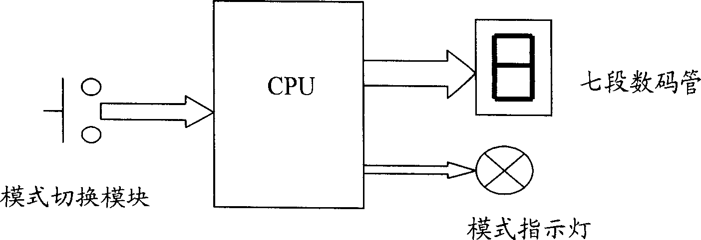
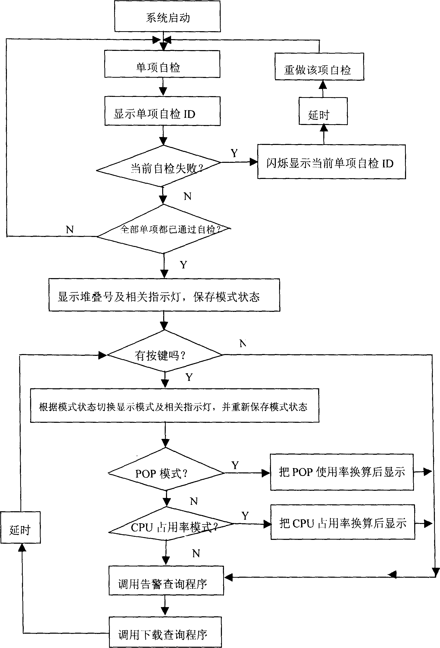
[0054] 1. When the device is working normally, that is, when there is no fault alarm or action expression, it displays normal device operation status information, including the display of POE power usage, CPU usage, and stack number, etc. See Table 1. In the mode of POE power usage rate and CPU usage rate, the POE utilization rate and CPU usage rate of the device are displayed in a seven-digit field from low to high. The five display states correspond to five percentage ranges. If the actual usage rate If the / utilization rate exceeds the rated / set value, all fields will be reminded by flashing. In stack mode, it displays the stack number of the current device, and if it works in stand-alone mode, it displays "1". For the aforementioned information display sequence, since they belong to the same priority, when displaying specific information, it is also necessary to switch modes through the mode switching module, so that the mode indicator light indicates the current correspon...


PUM


Abstract

This invention relates to a method and apparatus for realizing multi-meaning display by seven segment digital tubes. In data communication, by the nixie tube matched with mode indicator, it realizes system default alarm, action express and device state information by special display coding scheme and information priority to reduce cost for user request in real-time monitor.

Description


Claims


Application Information

Patent Timeline
Owner NEW H3C TECH CO LTD
Why Eureka
Try Eureka