
Power source board able to be controlled in zone

A technology of partition control and power board, applied in circuits, inductors, circuit devices, etc., can solve problems such as inability to supply power, no confirmation of load feedback information, and energy waste

Inactive Publication Date: 2006-09-20
CHONGQING UNIV
View PDF4 Cites 32 Cited by
  • Summary
  • Abstract
  • Description
  • Claims
  • Application Information

AI Technical Summary

Problems solved by technology

Another commonly used method is to keep the transmitting coil of the energy transmitting board in the state of load power supply, and it can work when there is a load, but there is a problem of energy waste in this way when there is no load
Although the Chinese patent CN1153230C involves the detection of electrical appliances, it is simply detected through the inductive coupling between the secondary coil on the main circuit side and the secondary coil of the load, and cannot transmit any signal related to the type and capacity of the load. Therefore, it only It can supply power according to a specific load capacity but not according to the needs of different loads, and it does not further confirm the information of the load feedback. As long as any object containing a coil is close to the device, it will supply power to the object

Method used


Image

  • Power source board able to be controlled in zone
  • Power source board able to be controlled in zone
  • Power source board able to be controlled in zone

Examples


Embodiment Construction

[0024] Below in conjunction with accompanying drawing, the specific embodiment of the present invention is described as follows:

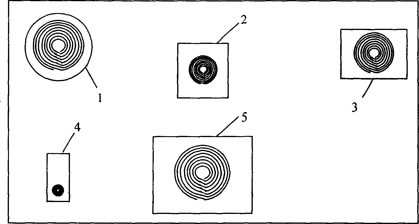
[0025] figure 1 It is a simple schematic diagram of the power transmitting board, where the desk lamp transmitting coil 1, the computer display device transmitting coil 2, the audio equipment transmitting coil 3, the mobile phone or shaver equipment transmitting coil 4, and the laptop computer transmitting coil 5 can be placed according to personal habits. , conforms to the viewpoint of ergonomics, and it can also be seen from the figure that the capacity of the load equipment is different, and the number of turns of the energy transmitting coil 10 is set differently. As long as the power required by the load is less than the power that the energy transmitting mechanism can provide, the load can work normally on the transmitting coil, such as a mobile phone load can normally work on the transmitting coil of the computer monitor.

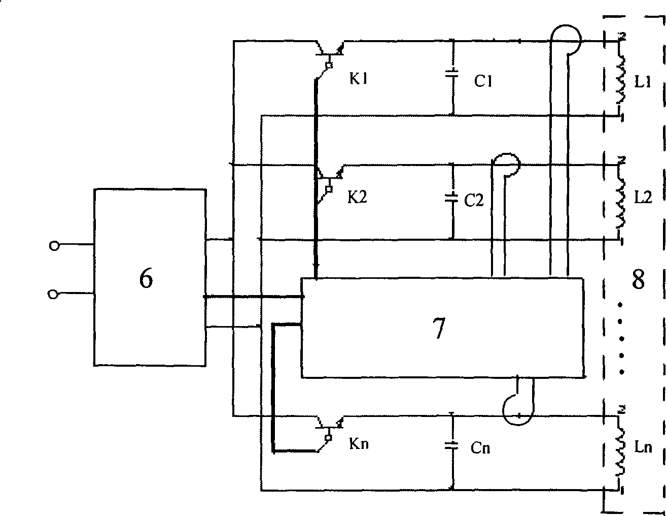
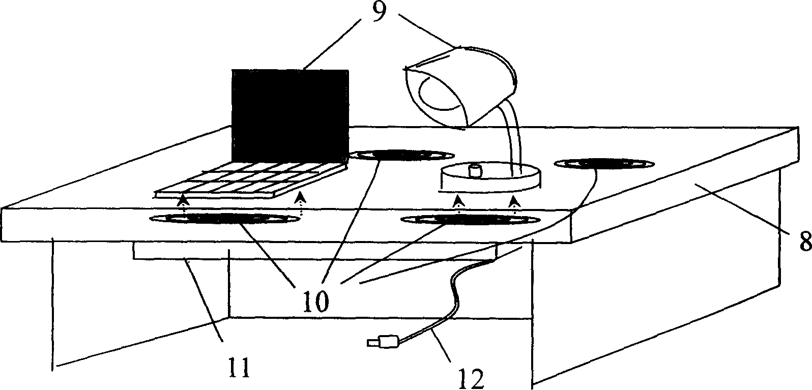
[0026] figure ...


PUM


Abstract

The power panel is composed of power transfer module, module for monitoring and controlling load, and energy emission plate. The power transfer module includes power transfer circuit, and intelligent control circuit. The module for monitoring and controlling load includes circuit of monitoring load, and circuit of receiving codes of loads, control circuit for transmitter coil, and circuit for outputting information of load. The energy emission plate includes transmitter coil of energy for multipartition and faceplate distributed according to conception of ergonomics. Loads are placed on power panel. Receiving electric energy from one route of conducting wire, the power panel supplies power for multiple loads in multipartition smartly and safely in non-electrical contact mode. Moreover, the power panel possesses function for controlling operation of transmitter coil based on result of discriminating the connected loads so as to make system work at optimization model.

Description

technical field [0001] The invention relates to a power supply board for non-contact electric energy transmission, in particular to a power supply board which adopts inductive electric energy transmission technology to provide electric energy for various household or office appliances in a non-electric contact manner. Background technique [0002] With the advancement of science and technology and the improvement of living standards, household electrical appliances and daily office equipment, especially portable equipment, are becoming more and more popular, and their power supply methods basically adopt the transmission method of direct conduction of contact electric energy. The power supply of electrical equipment such as computers and desk lamps is obtained from the power supply through wires and plugs. Another type of charging for portable electrical appliances such as mobile phones and mp3 players requires a power cord for connection. This way of taking power has potent...

Claims


Application Information

Patent Timeline
Patent Type & Authority Applications(China)
IPC IPC(8): H02J17/00H01F38/14H02J50/10
Inventor 孙跃苏玉刚
Owner CHONGQING UNIV
Learn More