


Quick Research
Generate reliable direction feasibility study reports for your R&D in just a few steps.

Technical Q&A
Discover and master advanced knowledge NOW. Basics, ideas, possibilities, all at once.

Find Solutions
As an expert in R&D theories, this can generate solutions to your technical problems instantly.

Evaluate Feasibility
Analyze your overall solution with one click, know your potential R&D risks in advance.

Monitor Landscape
Get weekly tech updates, stay abreast of the latest tech innovations and key insights.
Tool trolley
A technology for tool carts and bearing frames, which is applied in the manufacture of tools, workbenches, workshop equipment, etc., and can solve the problems that the support tripod does not have a safe positioning design, affects safety, and is difficult to locate.
- Summary
- Abstract
- Description
- Claims
- Application Information
AI Technical Summary
Problems solved by technology
Method used
Image

Examples
Embodiment Construction
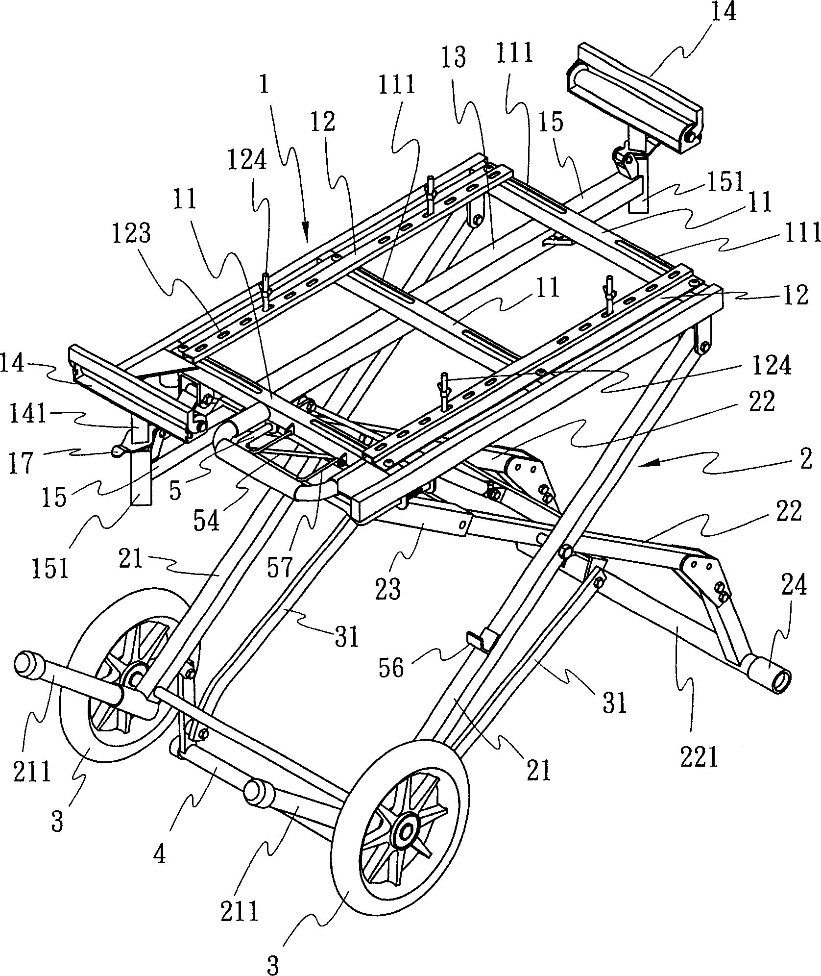
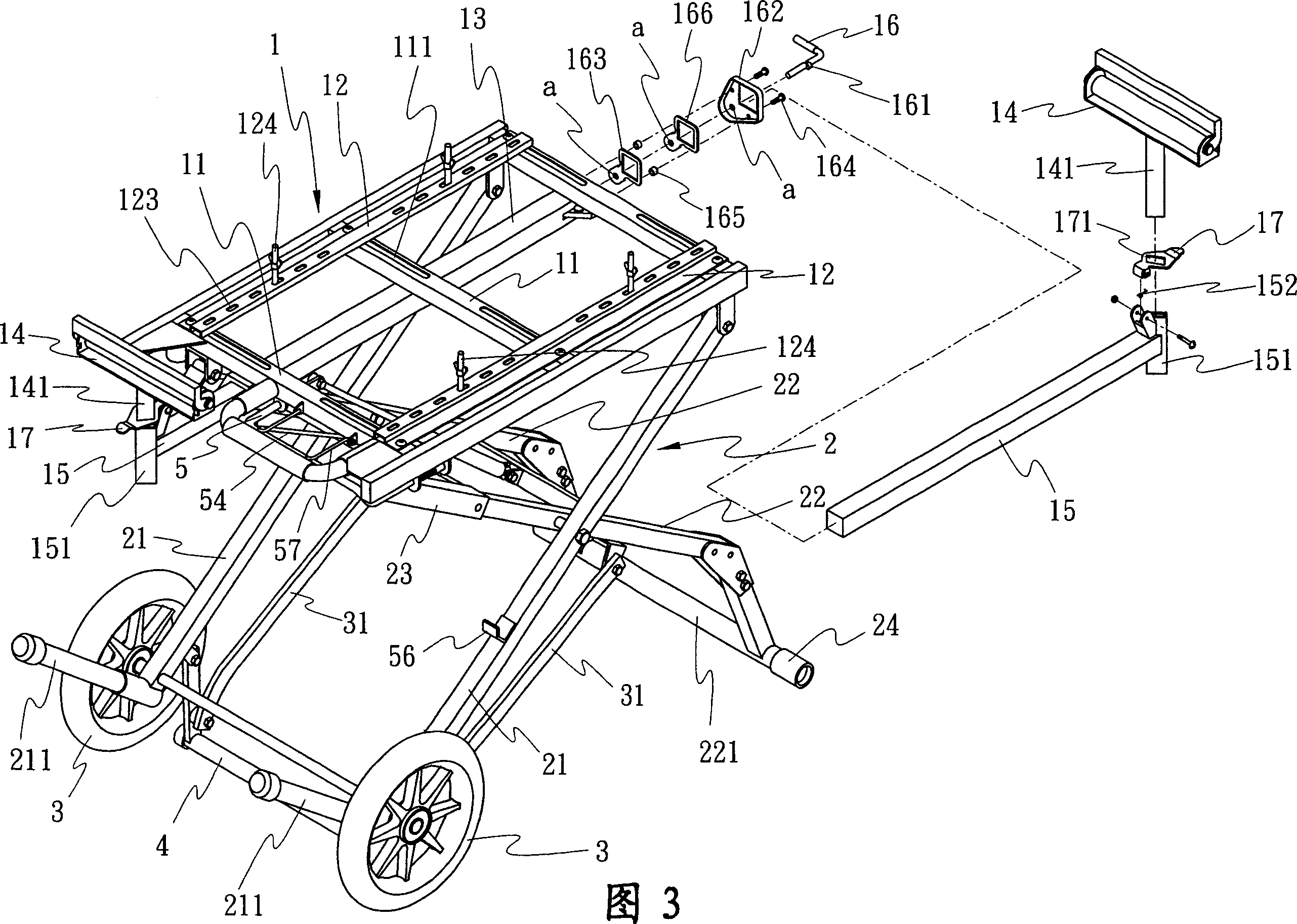
[0038] like figure 1 As shown, the tool cart of the present invention mainly includes: a carrier frame 1, a folding frame 2 and a group of front wheels 3, wherein:
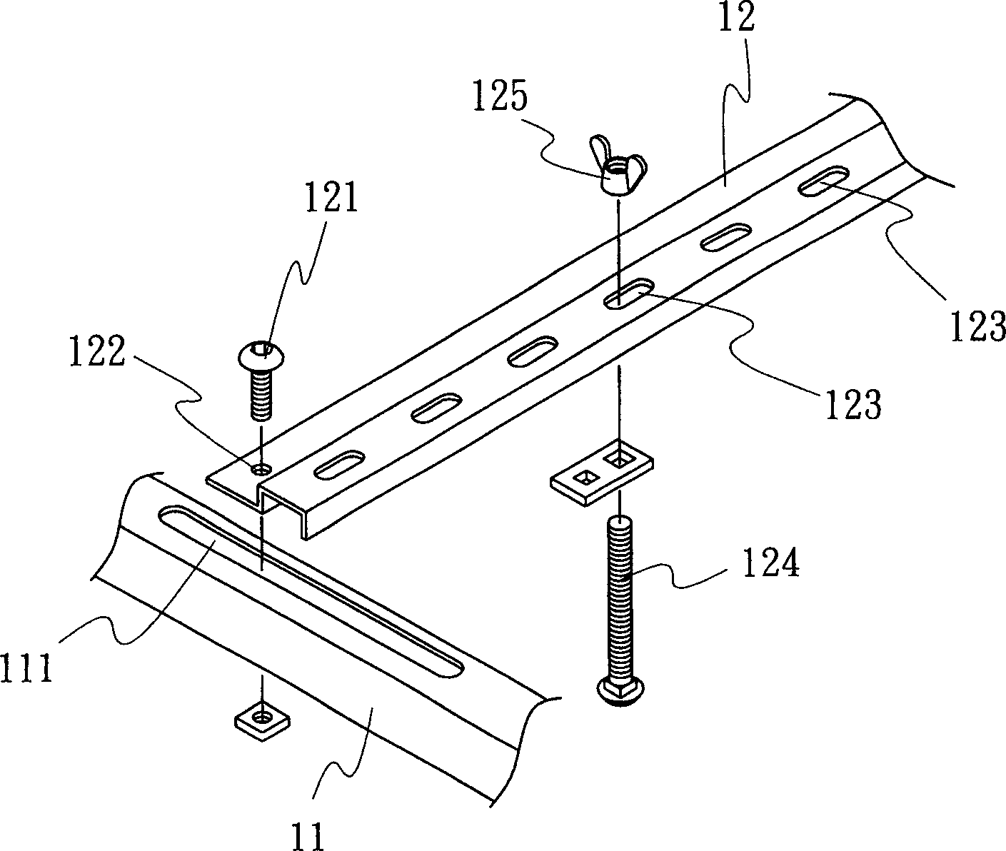
[0039] The carrying frame 1 is a frame, fixed on the upper end of the folding frame 2, and is specially used for locking and carrying the equipment (such as a sawing machine). The straight frame bar 12 of the side, the transverse frame bar 11 is provided with long slotted hole 111, makes the straight frame bar 12 of both sides move and adjust its locked position by bolt 121 (as figure 2 As shown), in addition to the through holes 122 that match the bolts 121, the vertical frame bar 12 is provided with a plurality of lock holes 123, so that the bolts 124 and wing nuts 125 can be arbitrarily selected through the lock holes 123 for locking , so that the bearing frame 1 can be locked by bolts 124 to suitably provide various sizes of implements;
[0040] The above-mentioned carrier 1 has a hollow tube 13 fixed in th...
PUM
 Abstract
Description
Claims
Application Information
 - R&D Engineer
- R&D Manager
- IP Professional
- Industry Leading Data Capabilities
- Powerful AI technology
- Patent DNA Extraction
Browse by: Latest US Patents, China's latest patents, Technical Efficacy Thesaurus, Application Domain, Technology Topic, Popular Technical Reports.
© 2024 PatSnap. All rights reserved.Legal|Privacy policy|Modern Slavery Act Transparency Statement|Sitemap|About US| Contact US: help@patsnap.com