
Electronic part feeder

A technology for electronic component supply and component application in the direction of electrical components, electrical components, etc., which can solve the problems of broken cover tape, inability to absorb electronic components, and inability to peel off stable cover tape, so as to avoid adsorption errors.

Inactive Publication Date: 2006-09-06
JUKI CORP
View PDF1 Cites 4 Cited by
  • Summary
  • Abstract
  • Description
  • Claims
  • Application Information

AI Technical Summary

Problems solved by technology

For example, when the winding force of the cover tape is strong, the breakage of the cover tape occurs, or conversely, when the winding force is weaker than the tape conveying force, the peeling cannot be performed because the cover tape enters under the tape guide. Either situation can lead to the inability to peel the cover tape from the carrier tape stably and not be able to adsorb the electronic components

Method used


Image

  • Electronic part feeder
  • Electronic part feeder
  • Electronic part feeder

Examples


Embodiment Construction

[0019] Embodiments of the present invention will be described in detail below with reference to the drawings.

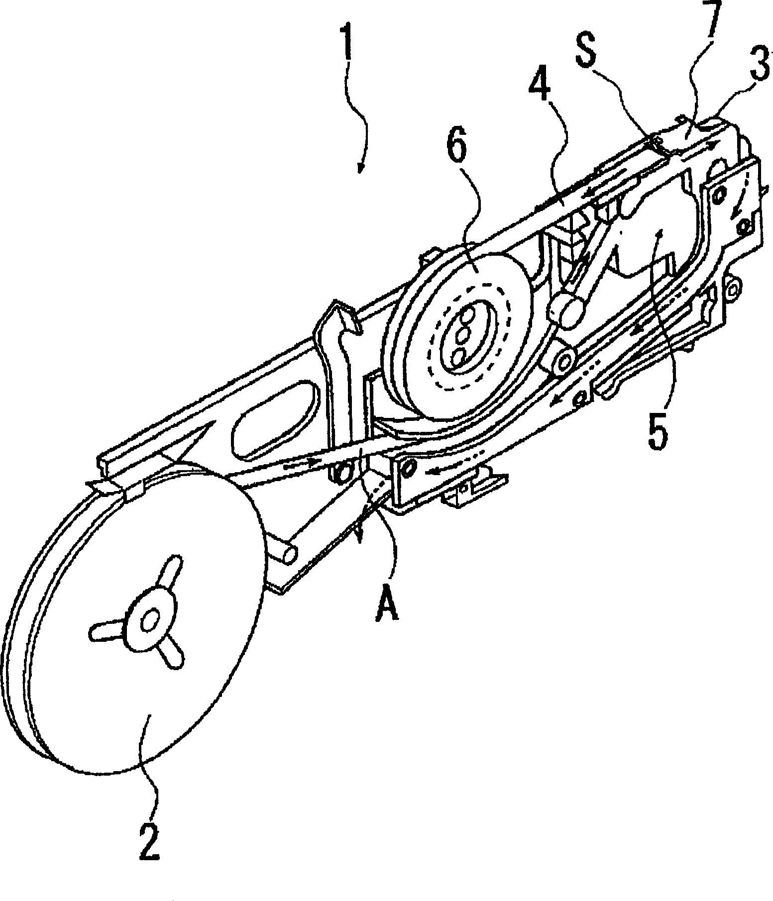
[0020] Such as figure 1 As shown, the parts supply device 1 of the present invention has: a take-up reel (reel) 2, which is detachably installed on the feeder (feeder bank) main body (not shown), for winding parts conveyor belt A; A conveying mechanism 5 for sending out a component conveying tape A composed of a carrier tape 3 and a cover tape 4 in a conveying direction; and a recovery take-up reel 6 for peeling and recovering the cover tape 4 from the carrier tape 3 .

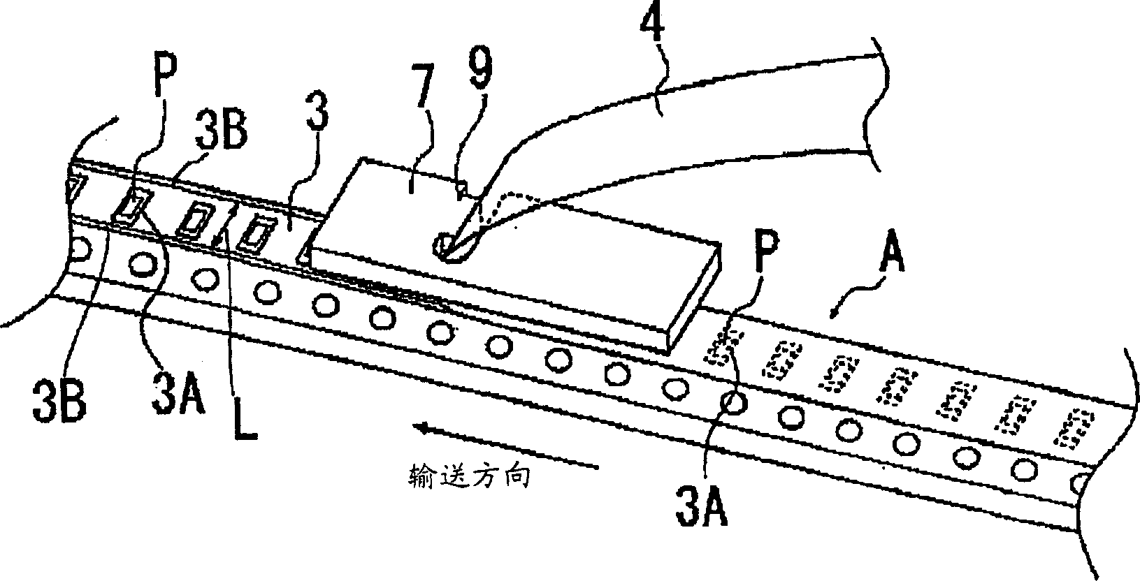
[0021] Such as figure 2 As shown, the carrier tape 3 stores all the electronic components P in a certain direction one by one in the storage chamber 3A formed at a certain pitch, and the cover tape 4 is spaced from the predetermined space on both sides of the carrier tape 3 in the longitudinal direction. The bonding portions 3B formed at intervals L are bonded to prevent movement or falling off. ...


PUM


Abstract

An electron-unit supply arrangement can prevent the paperfibre attached on the driving belt and the covering belt when detaching the covering belt from clinging to the projecting part. Accordingly, the covering belt can be smoothly detached from the driving belt, which can avoid the adsorptive error to the electron unit. The electron-unit supply arrangement includes: driving belt which takes in the units with equal interval and forms the bonding unit on the two edges along the direction of length with predetermined interval; covering belt which bonds with the said bonding unit of the driving belt; driver element which intermittently transports the driving belt; stripping element which detaches the covering belt from the driving belt; and winding element which can coil the covering belt separated from the driving belt. In the said electron-unit supply arrangement, the said stripping element includes a marginal element which detaches the covering belt from the driving belt; and a projecting part, in which the gap between the said projecting part and the said marginal element is set along the transfer direction of the driving belt and a straight-line element with a smaller gap than the said bonding unit of the driving belt is formed on the relative margin of the said marginal element.

Description

technical field [0001] The present invention relates to an electronic component supply device capable of peeling a cover tape (cover.tape) from a carrier tape that accommodates electronic components in a storage recess. Background technique [0002] According to the electronic component supply device described in Patent Document 1, as a unit for peeling the cover tape (top tape (top tape)) from the carrier tape, the cover tape is inserted into the slit provided in the tape guide, and the pair of slit end faces constituting the slit Peel the cover tape from the carrier tape. [0003] The notched end surface is configured such that the notched end surface on the conveying direction side (downstream side in the conveying direction) of the carrier tape is formed into an arc shape with an arbitrary curvature centered on the moving track of the electronic component of the carrier tape, so that the electronic component is pressed when the electronic component is adsorbed. By carry...

Claims


Application Information

Patent Timeline
IPC IPC(8): H05K13/02
Inventor 笹本宪一
Owner JUKI CORP
Learn More