
Automatic supply device for screw belt

A technology of automatic supply of screw straps, applied to screwdrivers, nailing tools, wrench, etc., can solve the problems of inaccurate locking position of screws, inaccurate displacement of screw straps, increased transmission gap, etc., and achieve the improvement of practical value , accurate locking, and the effect of reducing transmission error

Inactive Publication Date: 2006-09-06
陈河田
View PDF0 Cites 6 Cited by
  • Summary
  • Abstract
  • Description
  • Claims
  • Application Information

AI Technical Summary

Problems solved by technology

[0004] The biggest disadvantage of the above-mentioned "device that can automatically feed screw belts" is the use of gear teeth, while the biggest disadvantage of the "improved mechanism for screw feeder" is that the gears drive the screw belts. There will be a transmission gap, and when the teeth or gears drive the nail belt several times, the transmission gap will automatically increase, resulting in inaccurate displacement of the nail belt
Or because the positioning method is to use the positioning hole in the dial, but the inertia generated when the nail belt advances cannot be completely eliminated, resulting in the inaccurate locking position of the screw installed on the nail belt, which cannot be used for the screw. The screwdriver (bit) accurately drives the lock, causing troubles in use

Method used


Image

  • Automatic supply device for screw belt
  • Automatic supply device for screw belt
  • Automatic supply device for screw belt

Examples


Embodiment Construction

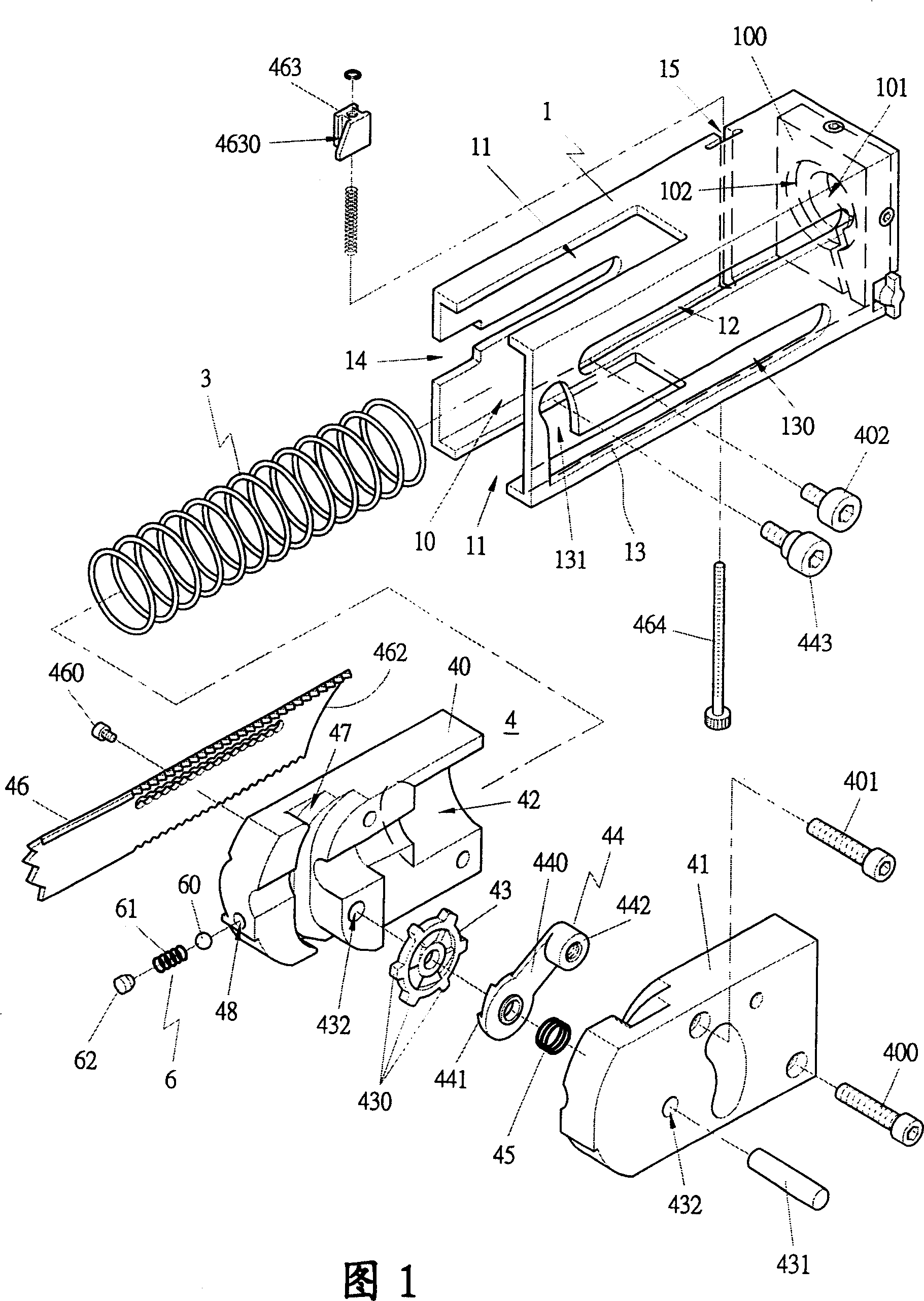
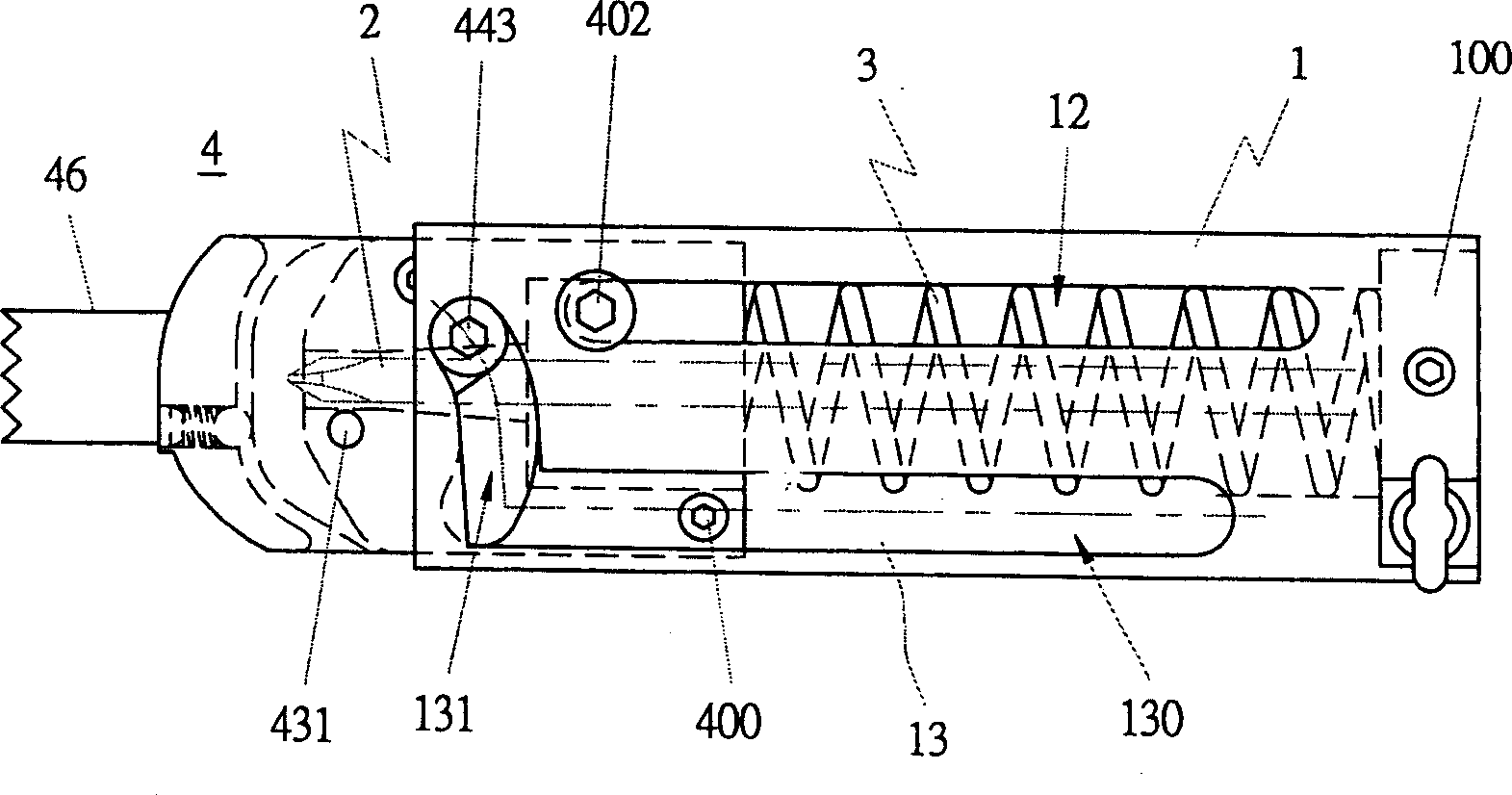
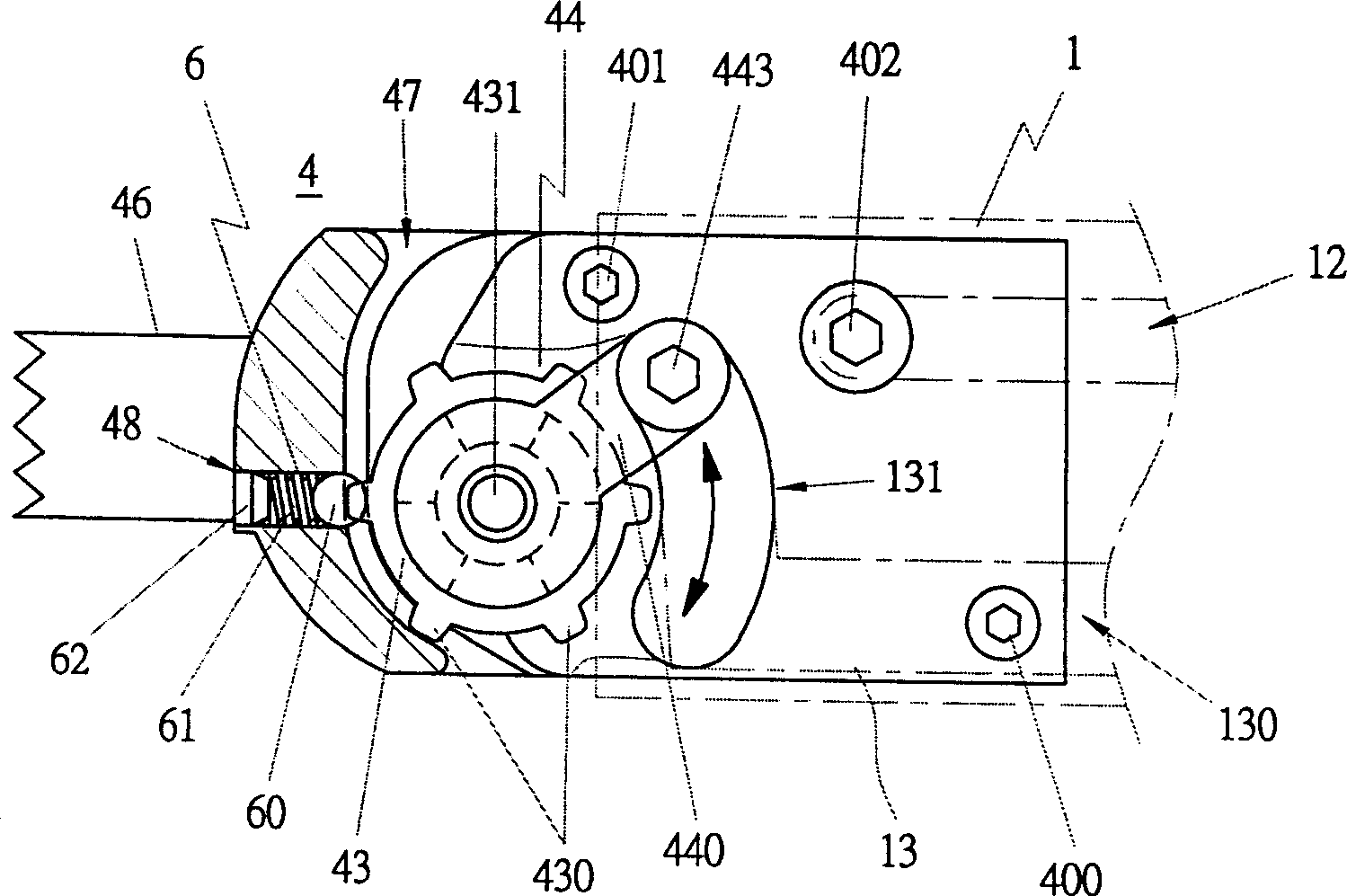
[0032] Figure 1, figure 2 , image 3 As shown, the present invention includes a body 1 , an elastic element 3 and a sliding block 4 .

[0033] The main body 1 is provided with a hollow groove 10 for the elastic element 3 and the sliding block 4 to be disposed, and a through hole 101 is provided on the rear wall 100 of the hollow groove 10 for a locking tool (bit) 2 to pass through to lock the screw. The rear wall of the hollow groove 10 is provided with an accommodating groove 102 for accommodating the elastic element 3 , so that one end of the elastic element 3 can be positioned against the top. The upper and lower walls of the body 1 are provided with slots 11 for the screw band 5 to facilitate the movement of the screw band 5 . The side wall of the main body 1 is provided with an orientation hole 12 and a driving hole 13 which is an elongated hole. The driving hole 13 has an elongated hole 130 and an arc-shaped hole 131 disposed at a front end of the elongated hole 130 ....


PUM


Abstract

The invention relates to a screw automatic feeding device, which can provides fixing auxiliary device to reduce transmission error and fixing the device accurately. The invention comprises: a main body, a flexible elements, a sliding block, and a positioning element for positioning the screw. The invention contains hollow groove to arrange the flexible element and sliding block; the side wall of main body has the directional hole to limit the sliding block and the driving hole to drive the sliding block; the flexible is between the main body and the sliding block; the transmission element that connected and driven b the main body driving hole is inside the sliding block, and the transmission wheel that connected and driven by the transmission element is inside the sliding block to drive the screw; the transmission element has the claw surface to unidirectional drive the transmission wheel; the transmission wheel has several transmission teeth; and the positioning element is arranged beside the sliding block.

Description

technical field [0001] The invention belongs to an auxiliary device for locking fasteners, in particular to an automatic supply device for screw tapes. Background technique [0002] The "device that can automatically dial the screw belt" disclosed in the announcement number 201953 is to set a dial at the end of the dial shaft, and the dial is evenly distributed with shifting teeth. In this way, when the rotating shaft of the dial rotates, the shifting teeth of the dial are used to drive the screw belt to move. [0003] The 'Screw Nail Feeder Improvement Mechanism' disclosed in Bulletin No. 537124 is equipped with a push nail group, which uses the protruding teeth on the push nail gear set inside the front end of the gun nozzle body to engage with the nail belt correspondingly, when the push nail group When the gear rotates, it can drive the nail belt to move at the same time. [0004] The biggest disadvantage of the above-mentioned "device that can automatically feed screw...

Claims


Application Information

Patent Timeline
IPC IPC(8): B25B23/04B25C1/00
Inventor 陈河田
Owner 陈河田
Learn More