High-speed knitter

一种高速编织机、机架的技术,应用在编织物、纺织品和造纸等方向,能够解决降低高速编织机耐用性、增加装配调整的难度、装配调整难度大等问题,达到降低加工成本和装配难度、降低装配难度、结构紧凑的效果

Active Publication Date: 2006-08-16
黎日佳
View PDF1 Cites 2 Cited by
  • Summary
  • Abstract
  • Description
  • Claims
  • Application Information

AI Technical Summary

Problems solved by technology

Although this high-speed knitting machine overcomes the shortcomings of bevel gear transmission, since each inner spindle support must be equipped with at least two transition gears, the number of transition gears is large, which increases the difficulty of assembly and adjustment, especially for several inner spindle supports. Tens or even hundreds of large high-speed knitting machines have more transition gears and more difficult assembly and adjustment
On the other hand, because the diameter of the transition gear is much smaller than that of the inner spindle drive disk, the speed of the transition gear is much higher than that of the inner spindle drive disk, and the transition gear is extremely easy to wear, which reduces the durability of the high-speed braiding machine

Method used


Image

  • High-speed knitter
  • High-speed knitter
  • High-speed knitter

Examples


Embodiment Construction

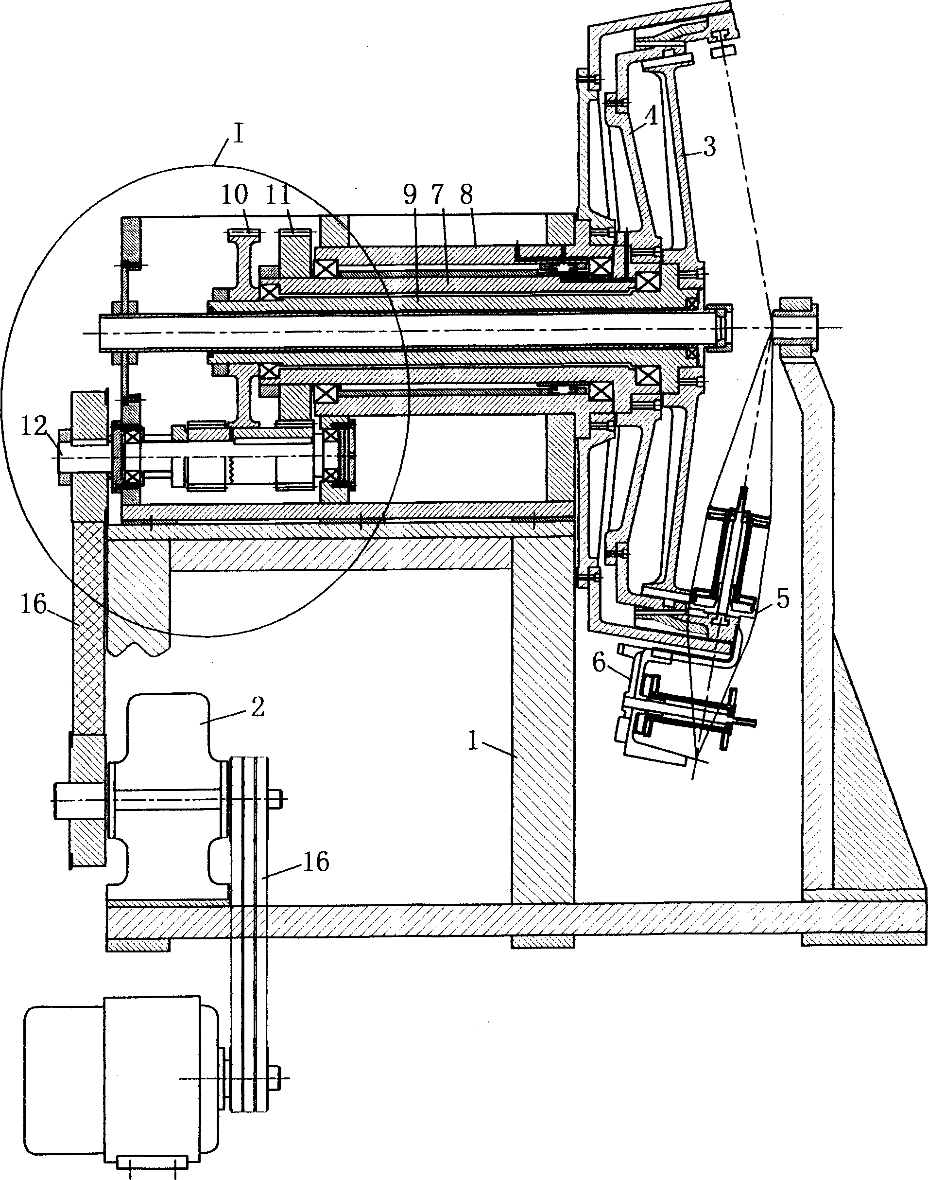
[0010] see Figure 1 to Figure 4 , The high-speed braiding machine includes a frame 1, a prime mover 2, an inner spindle drive disc 3 and an outer spindle drive disc 4. The prime mover 2 can usually adopt an electric motor. The inner ingot driving disc 3 and the outer ingot driving disc 4 respectively drive a plurality of inner ingot supports 5 and outer ingot supports 6 to rotate at high speed (in order to make the view clear, figure 1 Draw only one inner and one outer spindle holder). Outer ingot driving disc rotating shaft 7 is sleeved in an empty shaft sleeve 8 fixed with the frame. The inner ingot driving disc rotating shaft 9 is sleeved in the outer ingot driving disc rotating shaft 7 again. The inner ingot driving disc rotating shaft 9 is also a hollow shaft, which can be used for cables to run through it. Cylindrical gears 10, 11 are respectively installed on the ends of the inner ingot driving disc rotating shaft 9 and the outer ingot driving disc rotating shaft 7...


PUM


Abstract

A high speed braider is provided in the invention. The main arbor drive by the prime motor drives endo-exo ingot driving disk revolution axis through a suit column gear driving device which is composed of the mainshaft gear and two transition gears. The mainshaft gear engages with the column gear of one of the driving disk revolution axis, the two transition gears rotary with the same axis. One of which engages with the mainshaft gear and the other engages with the other column gear of the driving disk axis. The drive ratio of the mainshaft gear and the endo ingot driving disk axis is same as the mainshaft gear and the exo ingot driving disk axis. It can solve the problem of the bevel gear drive, and the transition gear needn't be installed between the endo ingot driving disk and the shelf. So it has improved the durability of the high speed braider.

Description

technical field [0001] The invention relates to cable manufacturing equipment, in particular to a high-speed braiding machine for braiding wire mesh layers on cables. Background technique [0002] A high-speed braiding machine for braiding wire mesh layers on cables, including a frame, a prime mover, an inner spindle drive disc and an outer spindle drive disc driven by the prime mover, and a plurality of inner spindle drive discs and outer spindle drive discs The disk drives the rotating inner and outer spindle holders. When the high-speed knitting machine is working, the prime mover drives a main shaft, the main shaft drives the inner and outer spindle drive discs to rotate, and the inner and outer spindle drive discs respectively drive multiple inner and outer spindle supports for reverse constant-speed revolution. In existing high-speed knitting machines, there are mainly two ways for the main shaft to drive the inner and outer spindle drive disks to rotate. One is to pr...

Claims


Application Information

Patent Timeline
Patent Type & Authority Applications(China)
IPC IPC(8): D04C3/40
CPCD04C3/44
Inventor 黎日佳
Owner 黎日佳
Why Eureka
Try Eureka