
Antenna system for a motor vehicle

An antenna system, technology for motor vehicles, applied to antennas, antennas, resonant antennas and other directions suitable for movable objects, can solve problems such as no one has raised, and achieve the effect of reducing costs

Inactive Publication Date: 2006-08-09
ADVANCED AUTOMOTIVE ANTENNAS
View PDF4 Cites 7 Cited by
  • Summary
  • Abstract
  • Description
  • Claims
  • Application Information

AI Technical Summary

Problems solved by technology

However, no one has proposed the use of this antenna structure for motor vehicles

Method used


Image

  • Antenna system for a motor vehicle
  • Antenna system for a motor vehicle
  • Antenna system for a motor vehicle

Examples


Embodiment Construction

[0059] The present invention describes an integrated multifunctional antenna system for a vehicle comprising at least one miniature antenna characterized by a space-filling curve. In another embodiment, refer to Figure 26-29 As described below, the microantenna can be characterized by a mesh size profile.

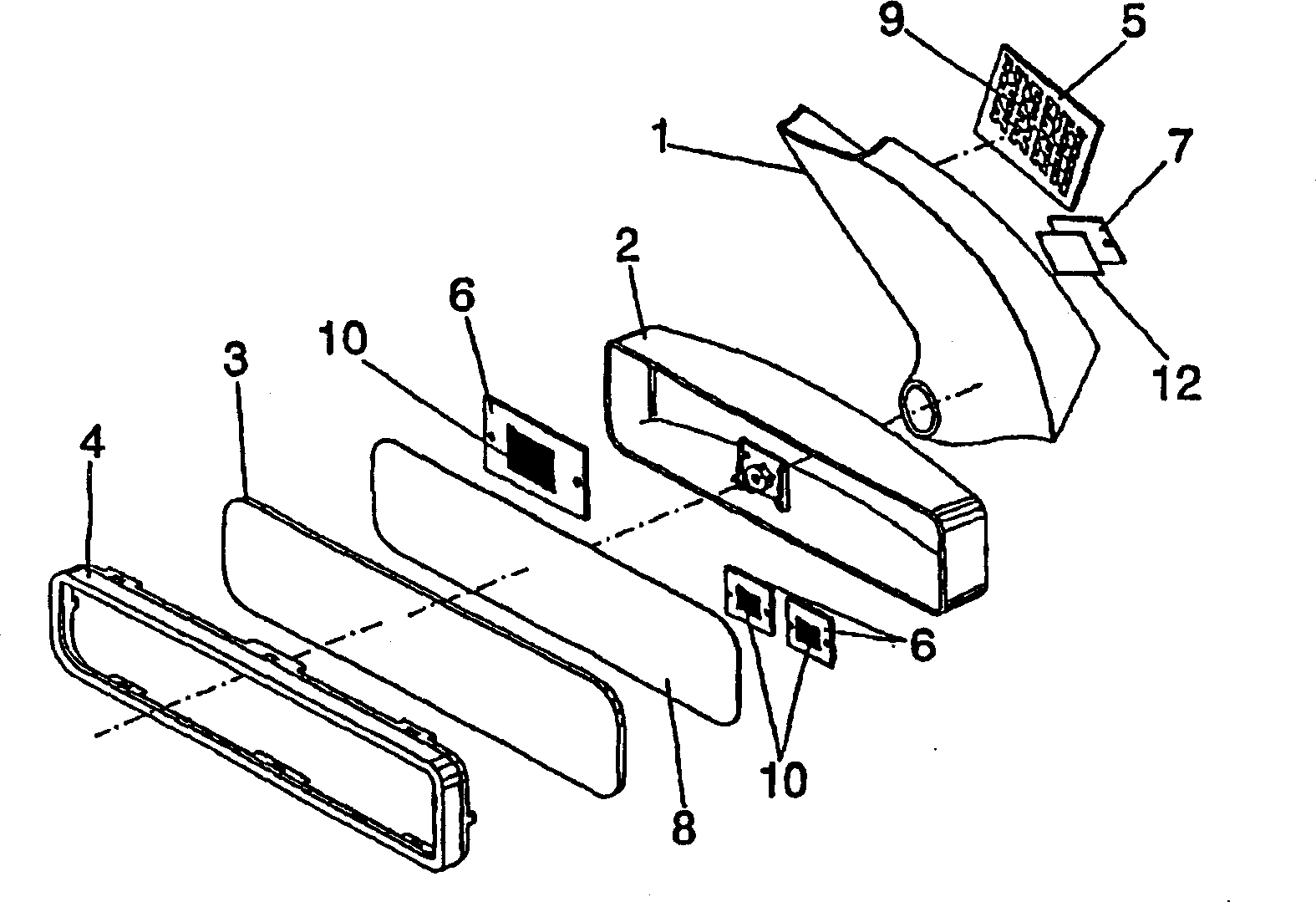
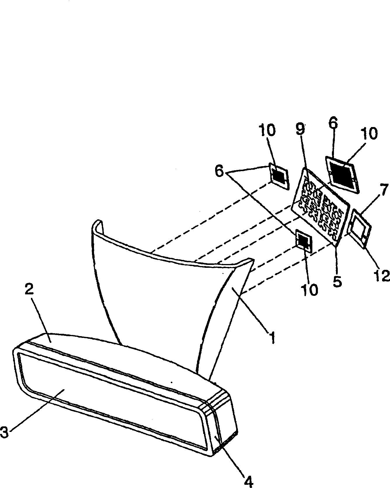
[0060] figure 1 A preferred embodiment of the invention is shown. The antenna system is integrated in an interior rearview mirror base support 1 and in the rearview mirror housing 2 . The system is surrounded by the mirror 3 and the mirror frame 4 . In this construction, the mirror base support 1 is provided as a vertical extension. Such a specific mirror component is shown to facilitate the understanding of the invention, but it does not form an essential part of the invention. Those skilled in the art will readily understand that other shapes of support members can be used within the spirit and scope of the present invention.

[0061]The antenna system includes a s...


PUM


Abstract

An integrated multi-service antenna system for a motor vehicle includes a plurality of antenna structures integrated within a physical component of the motor vehicle. The plurality of antenna structures includes a radio antenna and at least one of a cellular telephony antenna and a satellite-signal antenna. The radio antenna has a radiating arm, with at least a portion of the radiating arm defining a space-filling curve, the radio antenna further has a feeding point for coupling the radio antenna to a radio receiver in the motor vehicle.

Description

technical field [0001] The technology described in this patent application relates to the field of antennas. In particular, the application describes an antenna system for a motor vehicle. [0002] The invention relates to a multifunctional antenna system which can, for example, be integrated in a plastic cover fixed in the inner surface of a transparent windshield of a motor vehicle. [0003] The invention consists of a miniature antenna suitable for providing in a vehicle the basic service generally required, i.e. radio reception, preferably in the AM and FM or DAB (Digital Audio Broadcasting) band range, in the GSM 900, GSM 1800 and UMTS bands Send and receive mobile calls and GPS navigation systems within. [0004] The antenna shape and design is based on complex miniaturization techniques to greatly reduce the antenna size, making it possible to integrate it within a vehicle component, eg a rear view mirror. Background technique [0005] Until recently, the telecommu...

Claims


Application Information

Patent Timeline
Patent Type & Authority Applications(China)
IPC IPC(8): H01Q1/36H01Q1/38H01Q1/32H01Q1/12H01Q21/28B60R11/02H01Q1/22H01Q1/40H01Q1/42H01Q9/38H01Q9/42H01Q13/08
CPCH01Q21/28H01Q1/3266H01Q1/36H01Q1/1271H01Q1/3291H01Q1/3208H01Q1/38H01Q9/0428H01Q9/065
Inventor J·安古拉-普洛斯E·马丁纳兹-奥廷古萨C·普纳特-巴利阿达E·罗扎恩
Owner ADVANCED AUTOMOTIVE ANTENNAS
Learn More