
Section port body and vacuum cleaner

A suction port and mouth body technology, applied in vacuum cleaners, suction nozzles, cleaning equipment, etc., can solve the problems of inability to suction wall dust, low dust suction efficiency, and inability to effectively suction dust.

Inactive Publication Date: 2006-08-09
TOSHIBA LIFESTYLE PROD & SERVICES CORP
View PDF1 Cites 21 Cited by
  • Summary
  • Abstract
  • Description
  • Claims
  • Application Information

AI Technical Summary

Problems solved by technology

[0005] However, this kind of suction port body 1 is formed on the front of the suction port main body 4 due to the front wall portion 4A, and when the suction port body 1 is advanced, the front wall portion 4A will push the dust on the surface to be cleaned to the front, so There is a problem that the pushed out dust cannot be efficiently sucked, resulting in extremely low dust suction efficiency
In addition, since the bottom wall portion 4B is formed between the front edge 2a of the bottom surface suction port 2 and the front surface of the suction port main body 4, there is a problem that dust near the wall cannot be sucked.

Method used


Image

  • Section port body and vacuum cleaner
  • Section port body and vacuum cleaner
  • Section port body and vacuum cleaner

Examples


Embodiment Construction

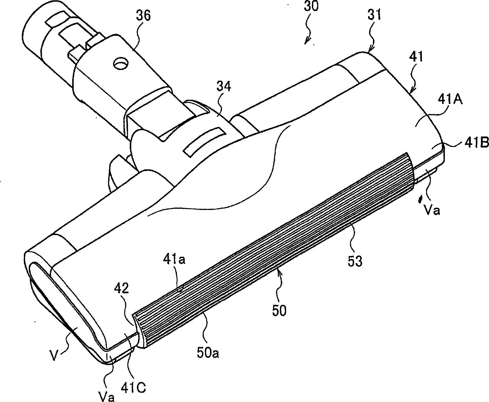
[0026] Hereinafter, embodiments of the suction port body and the vacuum cleaner using the suction port body according to the present invention will be described in detail with reference to the drawings.

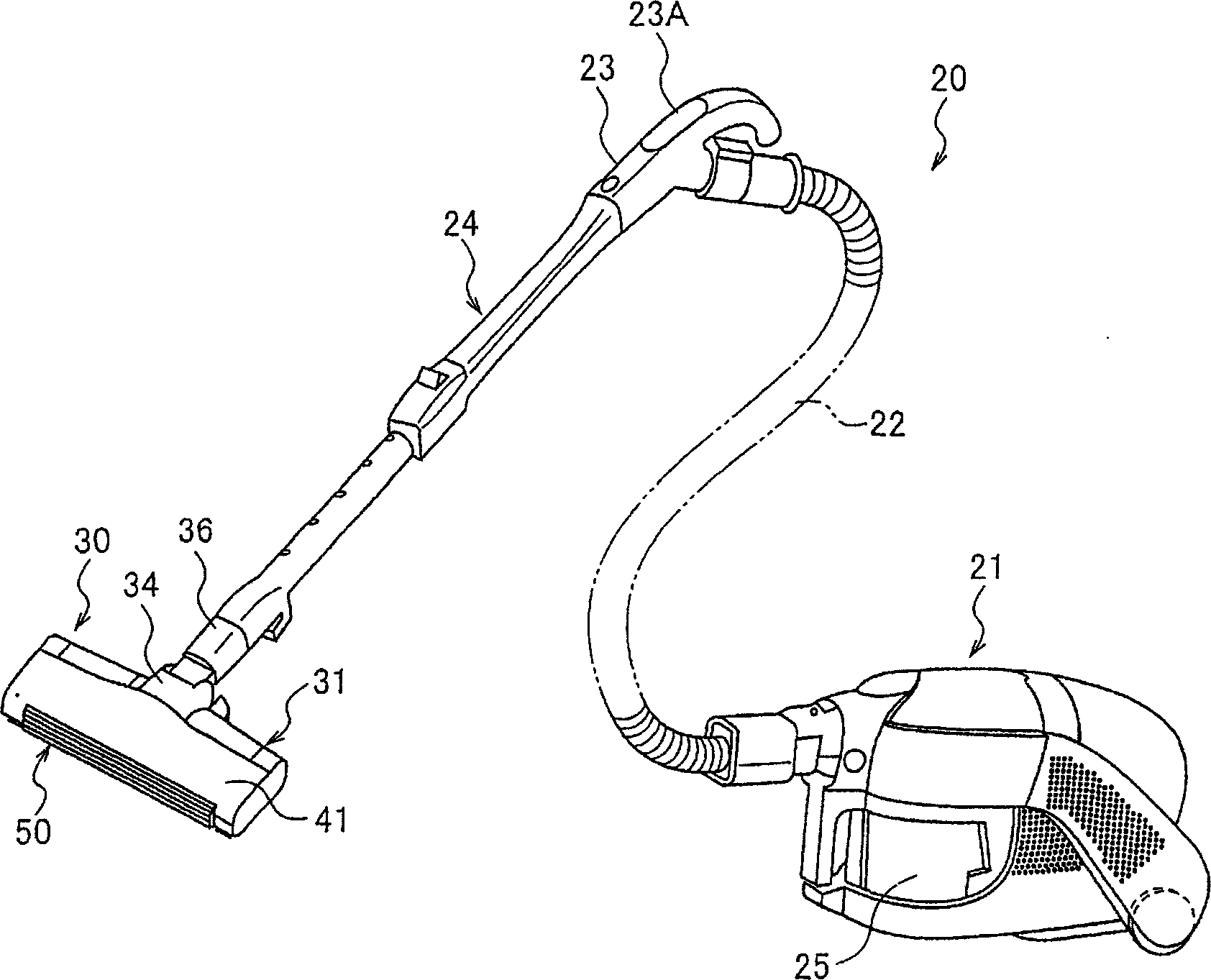
[0027] figure 1 It shows the vacuum cleaner 20 to which the suction port body 30 of this invention was applied. The vacuum cleaner 20 has: a vacuum cleaner main body 21; a hose 22, one end of which is connected to the vacuum cleaner main body 21 in a detachable manner; and an extension pipe 24, which is arranged on the other end of the hose 22 in a detachable manner The manual operation tube 23 is connected. The suction port body 30 is detachably connected to the front end portion of the extension pipe 24 .

[0028] The operation part 23A is provided on the manual operation pipe 23, has operation switches, operation buttons, etc. (not shown), and is used to operate the vacuum cleaner.

[0029] The vacuum cleaner main body 21 is provided with a dust collection container 25...


PUM


Abstract

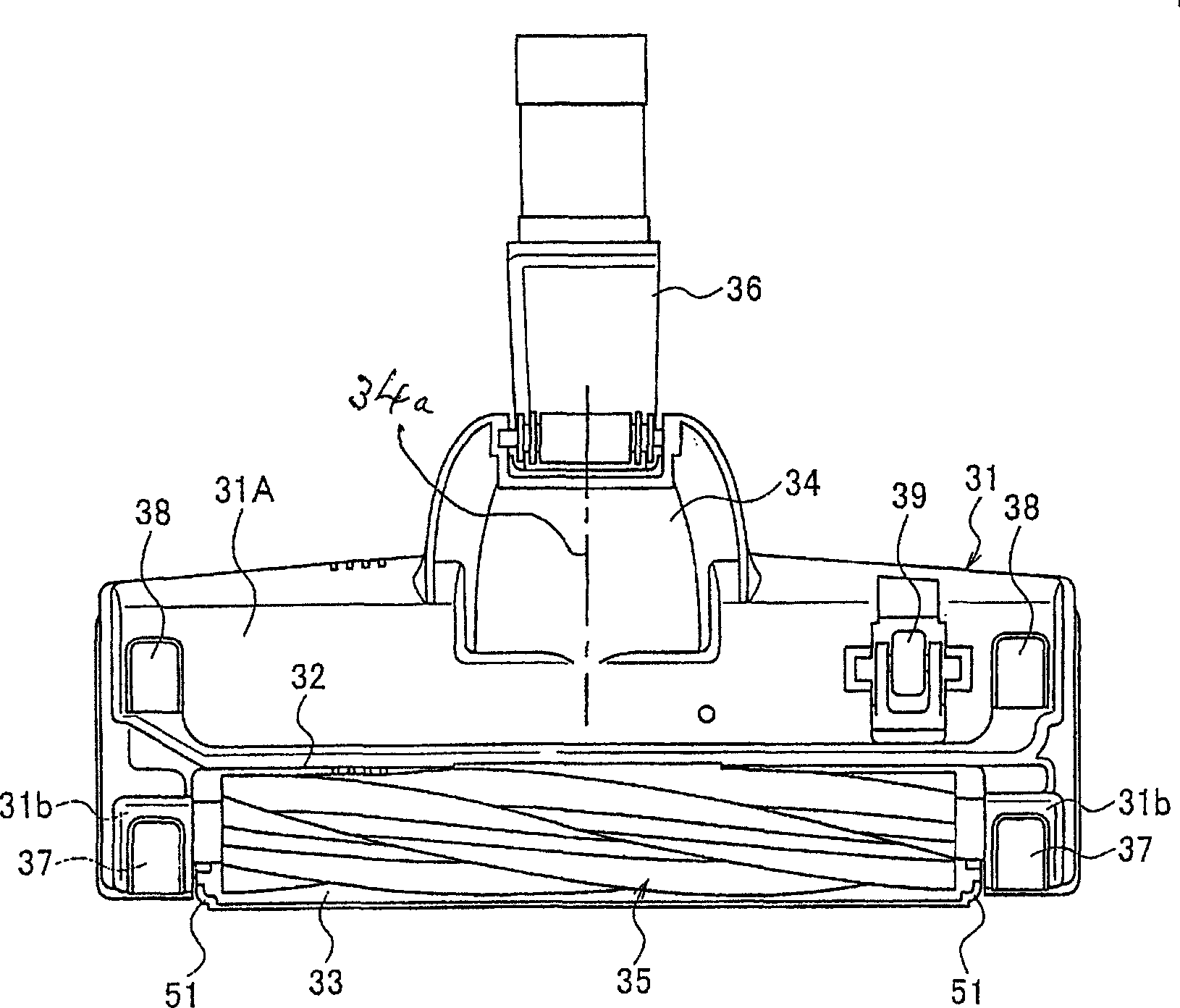
The present invention provides a suction port body (30), which has a suction port main body (31) with a bottom surface suction port (32) formed on the bottom surface of the suction port main body (31), and a suction port main body (31) formed on the front surface of the suction port main body (31). There is a front suction port (46) continuous with the bottom surface suction port (32), and a cover (50) covering the front suction port (46) is arranged, and the cover is movably arranged on the suction port main body (31) through an adjustment mechanism ), so that the front suction port (46) reaches a specific opening area, when the front of the cover (50) abuts against a wall or furniture, etc., the cover (50) moves to narrow the opening area of ​​the front suction port (46) .

Description

technical field [0001] The invention relates to a suction port body comprising a bottom surface suction port and a front suction port and a vacuum cleaner with the suction port body. Background technique [0002] In current vacuum cleaners, there are devices containing such as Figure 10 The suction port body of the structure shown (for example, refer patent document 1). [0003] The suction port body 1 has: a suction port main body 4 formed with a suction chamber 3 including a bottom surface suction port 2 on a bottom surface 1A; The rotating cleaning body 5 is driven by the air introduced from the air inlet 6 provided on the suction port main body 4, in a counterclockwise rotation mode ( Figure 10 middle) to rotate. [0004] According to this suction port body 1, since the dust adhering to the carpet is swept upward by the rotation of the rotary cleaning body 5, the dust can be efficiently sucked together with the air from the bottom surface suction port 2. [0005] How...

Claims


Application Information

Patent Timeline
Patent Type & Authority Applications(China)
IPC IPC(8): A47L9/02A47L9/04
CPCA47L9/02A47L9/0477A47L9/04
Inventor 内藤顺司市野雄之杉山善崇
Owner TOSHIBA LIFESTYLE PROD & SERVICES CORP
Learn More