Projection-type displaying device, its control method and control programe

A technology of a display device and a control method, which can be applied to projection devices, optics, instruments, etc., and can solve problems such as large power supply and lamp size, reduced conversion efficiency, and larger projection display devices

Active Publication Date: 2006-08-09
SEIKO EPSON CORP
View PDF1 Cites 4 Cited by
  • Summary
  • Abstract
  • Description
  • Claims
  • Application Information

AI Technical Summary

Problems solved by technology

[0006] However, when a thermal light source that generates heat as described above is used as an illumination light source, there are problems in that the conversion efficiency of converting input power into light is lowered, and the input voltage is high, resulting in increased power consumption.
In addition, the thermal light source also has the following problems: the size of the power supply and the lamp is large, the projection type display device becomes larger, and it is necessary to have an efficient cooling fan for cooling the thermal light source, and the noise due to the driving sound of the cooling fan becomes larger.
[0008] However, in this method, there are problems that a dichroic prism is required to make the light of each color emitted from the LED uniform, which increases the cost and increases the size of the projection display device.

Method used


Image

  • Projection-type displaying device, its control method and control programe
  • Projection-type displaying device, its control method and control programe
  • Projection-type displaying device, its control method and control programe

Examples


Embodiment Construction

[0053] Below, refer to figure 1 A projection display device, a control method thereof, and a control program thereof according to an embodiment of the present invention will be described through FIG. 5 .

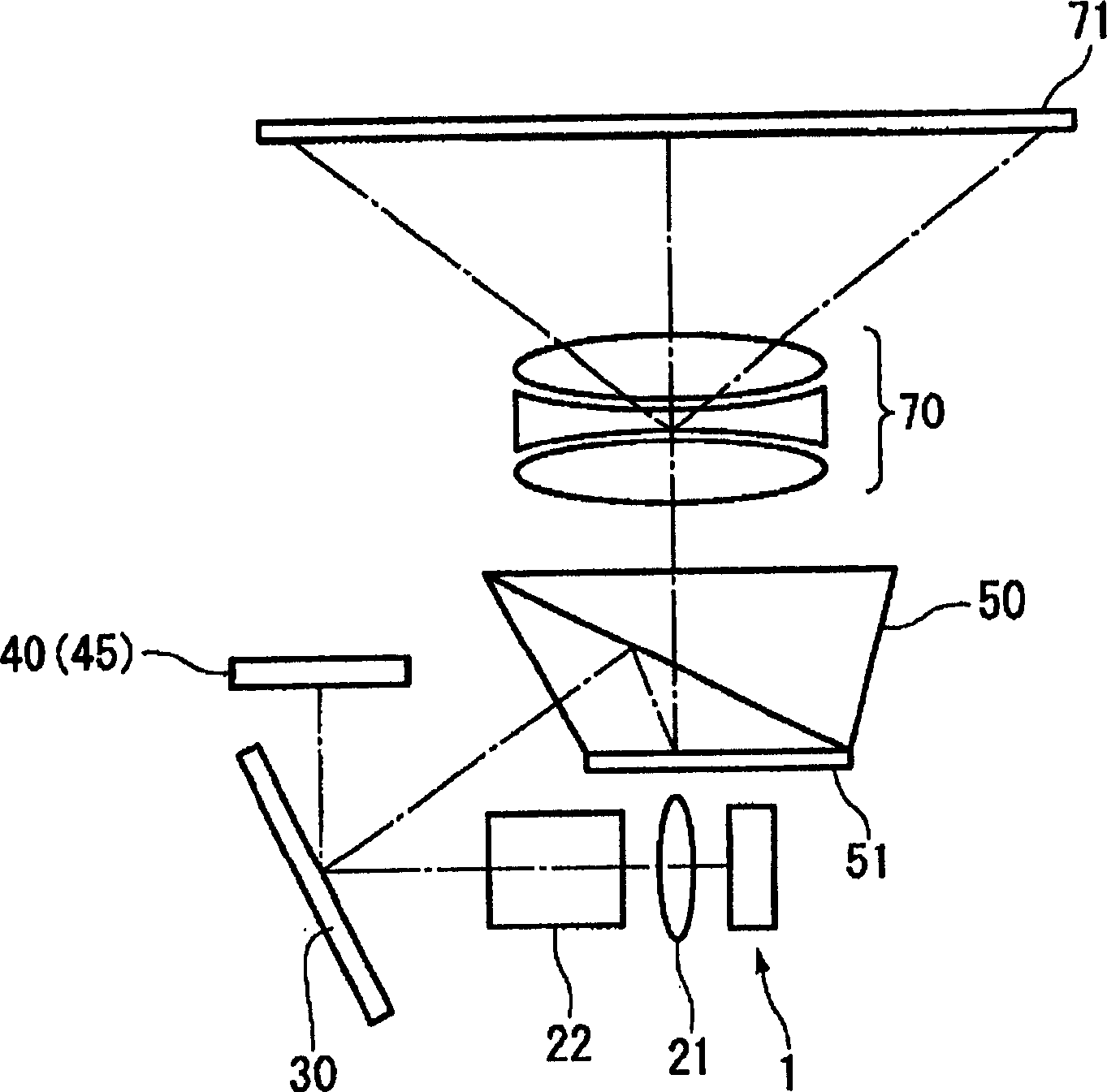
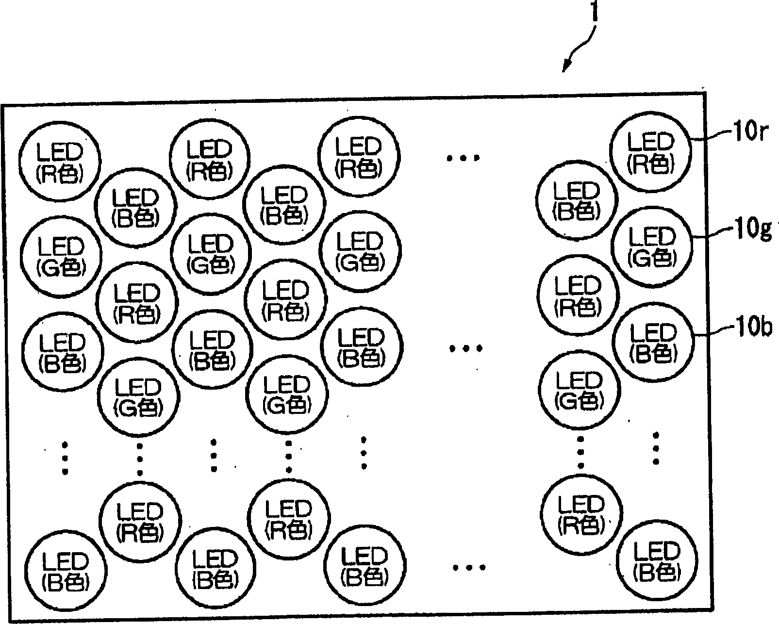
[0054] First, refer to figure 1 , a projection display device according to an embodiment of the present invention will be described. The projection type display device of this embodiment is a projection type color display device that displays color images by temporally modulating R (red), G (green), and B (blue) colored lights emitted from an LED array using a mirror device.

[0055] figure 1 It is a diagram showing the outline of a projection display device according to this embodiment.

[0056] Projection display devices such as figure 1 As shown, it is roughly composed of the following parts: an illumination device (solid-state light source array) 1, which emits different colored lights of R, G, and B; a mirror device 30, which performs time modulation on each colored...


PUM


Abstract

The invention realizes lightweight, minitype. Low power expenditure, low noise, and low cost of a projection type display device. Characters of the display device include following points: solid light source for emitting light; illuminator unit carries out time modulation for incident light by controlling direction of radiating the incident light; projection unit, and modulated light of projection.

Description

technical field [0001] The present invention relates to a projection display device, a control method for the projection display device, and a control program for the projection display device. Background technique [0002] [Patent Document 1] JP-A-2003-186110 [0003] [Non-Patent Document 1] "Nikkei Electronics", November 24, 2003, p.114. [0004] At present, as a light modulation device, in addition to a liquid crystal display device (LCD), for example, a projection display device (Projector) using a mirror device such as a DMD (Digital Micromirror Device, registered trademark) element of TI (Texas Instruments) is known. ). [0005] As the light source of this projection display device, a high-pressure mercury lamp that emits white light is generally used. The emitted white light is separated into R, G, and B colors in the direction of the time axis by using a color wheel, and each micromirror of the DMD element is used. The effective reflection time of each color is fu...

Claims


Application Information

Patent Timeline
Patent Type & Authority Applications(China)
IPC IPC(8): G03B21/00G03B21/14G02B27/18
Inventor 宫泽康永长谷川浩
Owner SEIKO EPSON CORP
Why Eureka
Try Eureka