
Pneumatic vacuum offset ink container

A technology of vacuum pneumatic glue and ink, which is applied in packaging, printing, and printing machines under vacuum/special atmosphere, which can solve the problems of ink adhesion, difficult operation, and high labor intensity of ink, and achieve the effect of saving ink

Inactive Publication Date: 2006-07-19
谭慈源
View PDF1 Cites 13 Cited by
  • Summary
  • Abstract
  • Description
  • Claims
  • Application Information

AI Technical Summary

Problems solved by technology

[0003] 1. The transportation is inconvenient, and it can only be placed flat during transportation and loading and unloading, otherwise the ink will leak due to the tilt or inversion of the tank body;
[0004] 2. The plastic film is used to cover and seal the packaging. The ink around the tank has a poor sealing effect and a chemical reaction with the air for a long time, resulting in skinning on the surface of the surrounding ink, which not only reduces the quality of the ink, but also causes waste;
[0005] 3. When in use, the ink is dug out by hand with a scraper, it is difficult to remove the ink in the tank, and some ink always adheres to the plastic film and the tank wall, causing considerable loss;
[0006] 4. The labor intensity of taking and supplying ink is high, especially in winter, when the temperature is low, the viscosity of the ink is high, the ink is hard, and the operation is more difficult;
[0007] 5. High energy consumption, high material consumption, complicated manufacturing process and high cost

Method used


Image

  • Pneumatic vacuum offset ink container
  • Pneumatic vacuum offset ink container
  • Pneumatic vacuum offset ink container

Examples


Embodiment Construction

[0027] The specific implementation of the vacuum pneumatic offset printing ink container of the present invention will be further described in detail below in conjunction with the accompanying drawings.

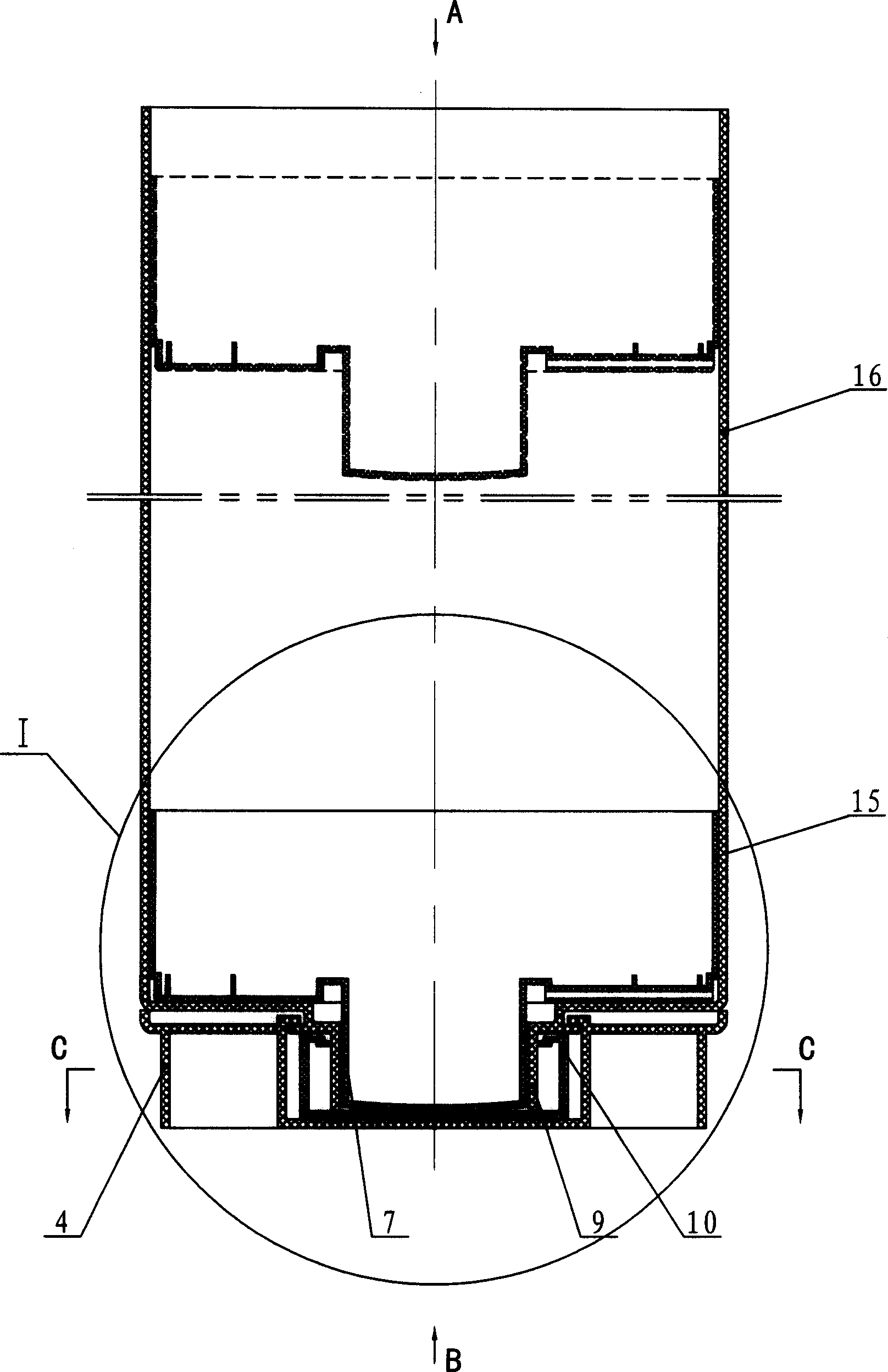
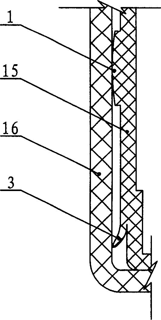
[0028] refer to Figure 1 to Figure 6 The vacuum pneumatic offset printing ink container of the present invention includes a cylinder body 16 and a piston 15 located therein, the ink is vacuum-packed in the space defined by the cylinder body 16 and the piston 15 , and the rear end is closed by the piston 15 . The front end of cylinder body 16 is provided with ink outlet 9, and inner cover 10 and outer cover 4 are housed on it. The front end surface of the piston 15 is provided with a boss 7 matching the inner hole of the ink outlet 9. When the printing machine needs to add ink, push the piston 15 to slide towards the ink outlet 9 and keep the ink container empty. 15 can not only scrape the ink off the inner wall surface of the cylinder 16 conveniently, but also when the pist...


PUM


Abstract

The invention discloses a vacuum pneumatic offset ink container, which consists of cylinder and piston in the cylinder, wherein the ink outlet is opened on the front end of cylinder with inner lid on the ink outlet; the projected-column is set on the front end of piston to match the ink outlet; the air guide hole is set in the front end wall of piston; the inlet of air guide hole lies on the front end of piston and the outlet lies on the peripheral side face of piston. The container can adjust the ink, which realizes vacuum package and storage due to draining the air between piston and ink.

Description

technical field [0001] The invention relates to an ink container, in particular to a vacuum pneumatic offset printing ink container which can be used in offset printing and can be vacuum-packed and stored, and the ink can be ejected pneumatically. Background technique [0002] In the printing industry, the traditional offset printing ink packaging container is a cylindrical iron can formed by pressing tinplate. It consists of two parts: the tank body and the upper cover. Put the lid on. This kind of offset printing ink tin can container packaging has the following disadvantages: [0003] 1. The transportation is inconvenient, and it can only be placed flat during transportation and loading and unloading, otherwise the ink will leak due to the tilt or inversion of the tank body; [0004] 2. The plastic film is used to cover and seal the packaging. The ink around the tank has a poor sealing effect and a chemical reaction with the air for a long time, resulting in skinning on...

Claims


Application Information

Patent Timeline
IPC IPC(8): B41F31/02B41F7/02B41F7/20B65D83/76B65D81/20B65D53/00
Inventor 谭慈源
Owner 谭慈源
Learn More