Rotary fluid machinery

A technology of fluid machinery and rotation phase difference, which is applied in the direction of rotary piston machines, mechanical equipment, rotary piston pumps, etc., can solve the problems of restricting the design freedom of the high pressure port 58, the influence of high efficiency maintenance, and the reduction of compression efficiency, etc., to achieve Securing the degree of freedom in design, suppressing the increase of useless space, and avoiding the effect of increasing pressure loss

Inactive Publication Date: 2006-07-12
DAIKIN IND LTD
View PDF1 Cites 5 Cited by
  • Summary
  • Abstract
  • Description
  • Claims
  • Application Information

AI Technical Summary

Problems solved by technology

[0005] In this way, there is the following problem: I am afraid that while restricting the degree of freedom in the design of the high-pressure port 58, etc., it will lead to a decrease in compression efficiency.
In this way, the useless space unrelated to compression increases, resulting in a reduction in compression efficiency
[0009] Therefore, there is a problem that, even if it is intended to reduce costs by commonizing the roller 54a, the degree of freedom in design such as the high-pressure port 58 is restricted, thereby affecting the maintenance of high efficiency.

Method used


Image

  • Rotary fluid machinery
  • Rotary fluid machinery
  • Rotary fluid machinery

Examples


no. 1 Embodiment

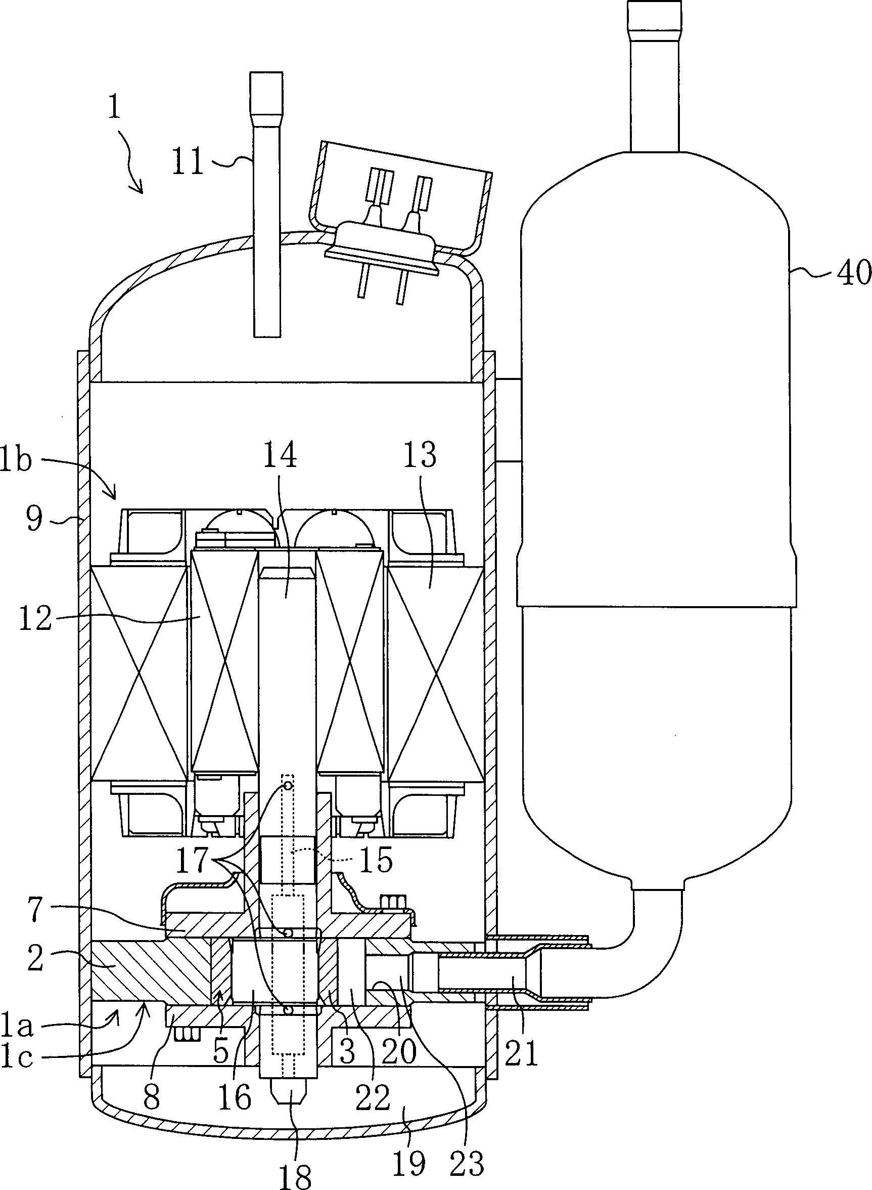
[0045] Such as figure 1 As shown, the rotary fluid machine according to the first embodiment of the present invention is composed of, for example, a rotary compressor 1 installed in a refrigeration device (not shown), and a compression mechanism 1a is accommodated in a hermetic container 9 and a compressor for driving the rotary compressor 1 is provided. Drive mechanism 1b for compression mechanism 1a.

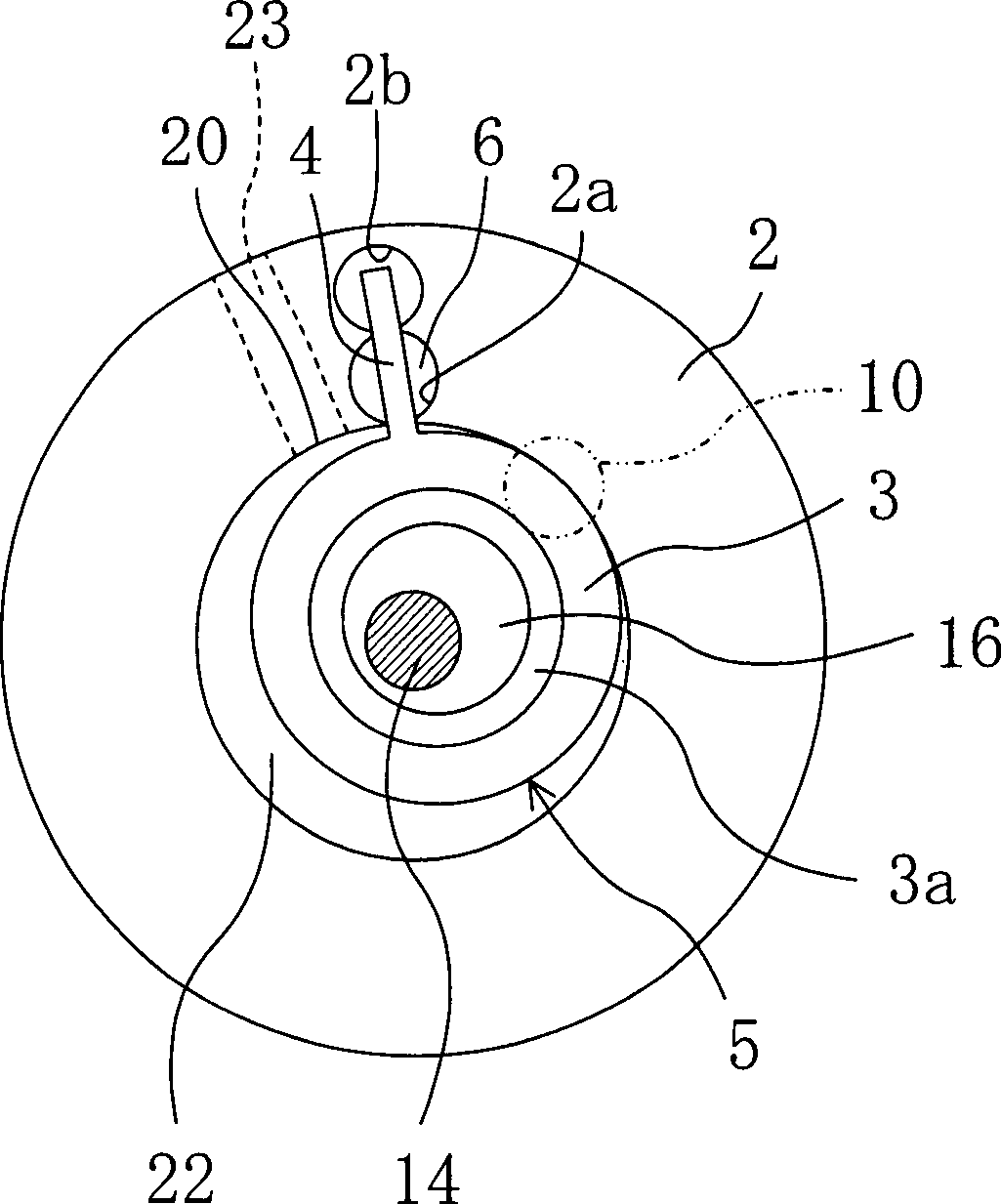
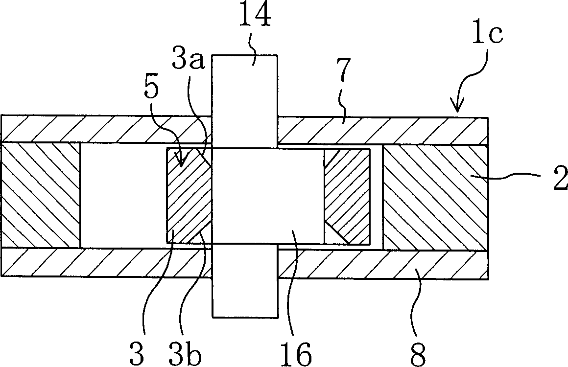
[0046] Such as figure 2 and image 3 As shown, the compression mechanism 1a includes a cylinder 1c and a piston 5 accommodated in the cylinder 1c. The cylinder 1 c includes a cylindrical cylinder body 2 , and a front head 7 and a rear head 8 as plates provided at both upper and lower ends of the cylinder body 2 .

[0047] The piston 5 is provided in the cylinder body 2 and is formed by integrally forming a cylindrical roller 3 and a flat blade 4 extending radially outward from the roller 3 . The piston 5 is made of sintered alloy. That is, in the first embodiment, the r...


PUM


Abstract

Rotary fluid machinery, wherein a cylinder body (2) is held by a front head (7) and a rear head (8), and a high-pressure port is formed in the front head (7). The both upper and lower end face widths of the roller (3) of a piston (5) are different from each other. The roller (3) is disposed in the cylinder body (2) so that the side thereof with a larger end face width is positioned on the front head (7) side.

Description

technical field [0001] The present invention relates to a rotary fluid machine, and more particularly, to a rotary fluid machine with measures to increase efficiency. Background technique [0002] Conventional technology related to rotary compressors used in refrigerating and air-conditioning applications is disclosed, for example, in JP-A-2000-23452. In this rotary compressor, an engine and a compression element that transmits the rotational force of the engine through a crankshaft and compresses refrigerant gas are provided in a housing. Such as Figure 13 and Figure 14 As shown, the compression element is configured by closing both ends of a cylindrical cylinder 51 with plates 52 and 53, and a piston 54 integrally formed with a roller 54a and a vane 54b is provided inside. A compression chamber 60 is defined by the cylinder 51 , plates 52 and 53 , and the piston 54 among the compression elements. A low-pressure port 56 is formed in the cylinder 51 , and a high-pressur...

Claims


Application Information

Patent Timeline
Patent Type & Authority Applications(China)
IPC IPC(8): F04C18/32F04C18/356F04C23/00
CPCF04C18/3562F04C18/322F04C23/008F04C29/12F04C23/001
Inventor 栗田慎上野广道
Owner DAIKIN IND LTD
Why Eureka
Try Eureka