Inserting strip sewing machine

A sewing machine and molding technology, which is applied to sewing machine components, sewing equipment, cloth feeding mechanism, etc., can solve the problems of bulky and inconvenient cloth feeding mechanism with large presser feet, and achieve the effect of improving workability and reducing the number of parts

Active Publication Date: 2006-07-12
JUKI CORP
View PDF1 Cites 6 Cited by
  • Summary
  • Abstract
  • Description
  • Claims
  • Application Information

AI Technical Summary

Problems solved by technology

[0008] As a result, the cloth feeding mechanism of the large presser foot becomes larger, resulting in the larger size of the panel sewing machine as a whole, causing inconvenience

Method used


Image

  • Inserting strip sewing machine
  • Inserting strip sewing machine
  • Inserting strip sewing machine

Examples


Embodiment Construction

[0024] (Overall configuration of the embodiment of the present invention)

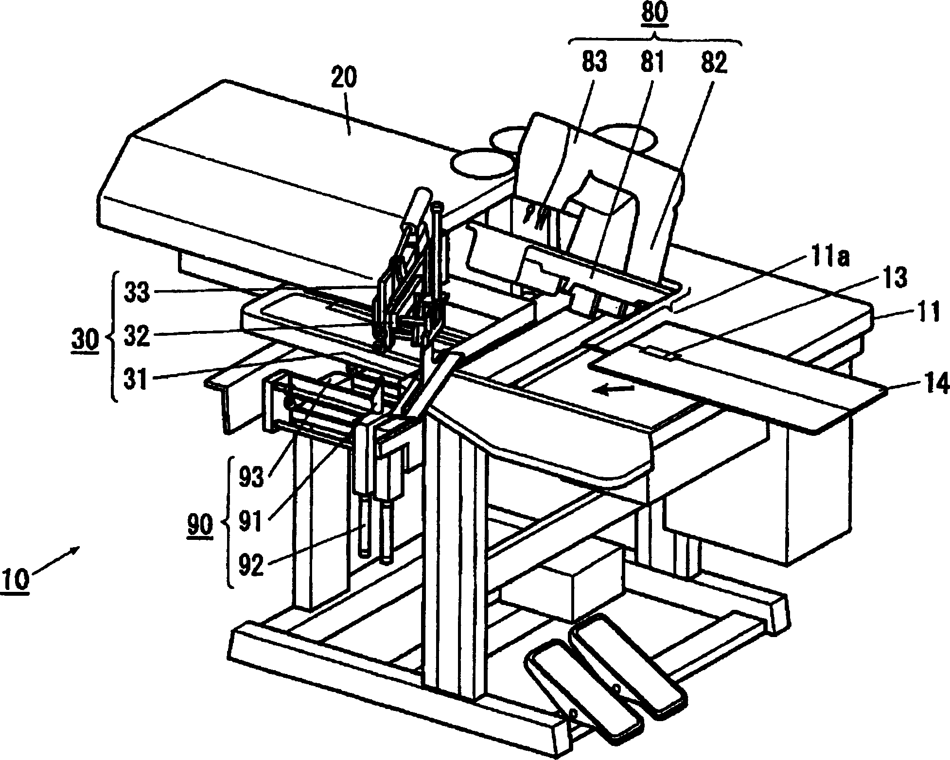
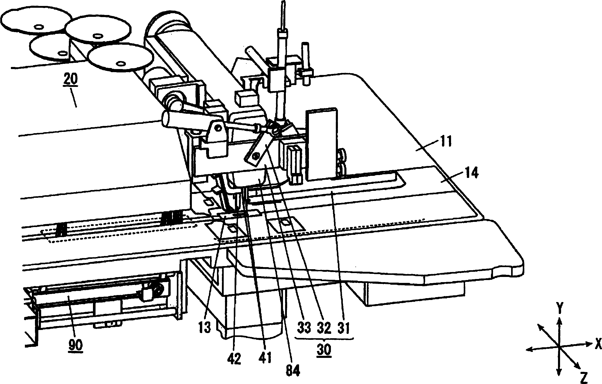
[0025] Below, based on Figure 1 to Figure 5 , an embodiment of the present invention, that is, a panel sewing machine 10 will be described. figure 1 as well as figure 2 It is a perspective view showing the overall schematic configuration of the panel sewing machine 10 . And in this embodiment, each direction is determined on the basis of the XYZ axes shown in each figure, the Z-axis direction is consistent with the up-and-down movement direction of the movable cutter 42 described later, and the plane on which the sewing operation is performed is consistent with The Z-axis direction is vertical, the direction of cloth feeding parallel to the working plane is defined as the X-axis direction, and the direction perpendicular to the X-axis direction parallel to the working plane is defined as the Y-axis direction.

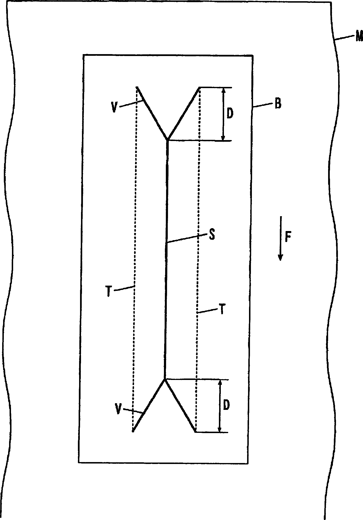
[0026] image 3 It is an explanatory diagram showing the arrangement relationship of t...


PUM


Abstract

To restrain a bad effect of throwing down a sewing machine frame forward. This binding sewing machine comprises: a needle vertical motion mechanism for moving up and down a sewing needle 41; a shuttle mechanism for entangling a sewing thread passed through the sewing needle in a bobbin thread; a driving motor 15 serving as a driving source of the needle vertical motion mechanism and the shuttle mechanism; a sewing machine frame 80 holding the respective components; and a table 11 holding the sewing machine frame in its placed state, wherein an output shaft of the driving motor is directly connected to one end part of a lower shaft, a motor block 85 holding the driving motor is fixed and mounted on the lower side of the end of a vertical cylinder part 82 side of the sewing machine frame, and the motor block 85 is provided with a support shaft 86 rockably supporting the sewing needle side end part of the sewing machine frame to move up and down.

Description

technical field [0001] The invention relates to a panel sewing machine which sews panel cloth on the upper body of clothes, and forms slits on the upper body panel and the panel fabric to form pockets. Background technique [0002] In the sewing of the conventional panel sewing machine, the upper part of the body and the panel fabric on it are stacked on the upper surface of the needle plate, and the bottom plate part and the vertical plate part erected perpendicularly to the top of the bottom plate part are placed on it. The formed section is an inverted T-shaped hemming machine. Moreover, both ends of the panel cloth are kept in the state of returning from the upper surface of the bottom plate of the hemming machine along the planes of the vertical plate, and each side is conveyed in a predetermined direction on the large presser foot cloth feeding mechanism. Cloth, one side is sewn with two needles on both sides of the vertical board section of the hemming machine. More...

Claims


Application Information

Patent Timeline
Patent Type & Authority Applications(China)
IPC IPC(8): D05B35/06D05B37/04
Inventor 沟渕顺也小川达矢高濑秀纪平泽裕
Owner JUKI CORP
Why Eureka
Try Eureka