Liquid crystal panel and liquid crystal display apparatus
A technology of liquid crystal panel and liquid crystal layer, which can be used in identification devices, televisions, optics, etc., and can solve problems such as insufficient improvement of oblique contrast ratio.
- Summary
- Abstract
- Description
- Claims
- Application Information
AI Technical Summary
Problems solved by technology
Method used
Image

Examples
preparation example Construction
[0242] Preparation of anode plate A
[0243] [Reference Example 1]
[0244] A commercially available polymer film "ARTON G" (trade name, thickness 100 μm, glass transition temperature 171°C, weight average molecular weight 130,000, JSR Provided by Co., Ltd.) was uniaxially stretched 1.30 times in the longitudinal direction at 175°C (temperature measured at a distance of 3 cm from the back of the film, with a temperature fluctuation of ±1°C) in an air-circulating constant temperature furnace while fixing the longitudinal direction of the film to make a phase Poor film A. Table 1 shows the properties of the retardation film A obtained. Re[590] of the polymer film (before stretching) was 3 nm and Rth[590] was 7 nm.
[0245] [Reference Example 2]
[0246] As the retardation film B, a commercially available polymer film "Pureace WR" (trade name, thickness 78 μm, supplied by Teijin Corporation) containing polycarbonate as a main component and having a fluorene structure in the m...
Embodiment 1
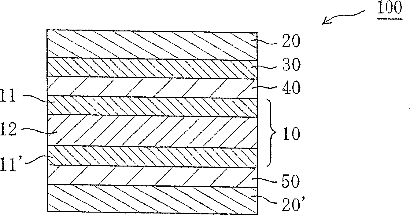
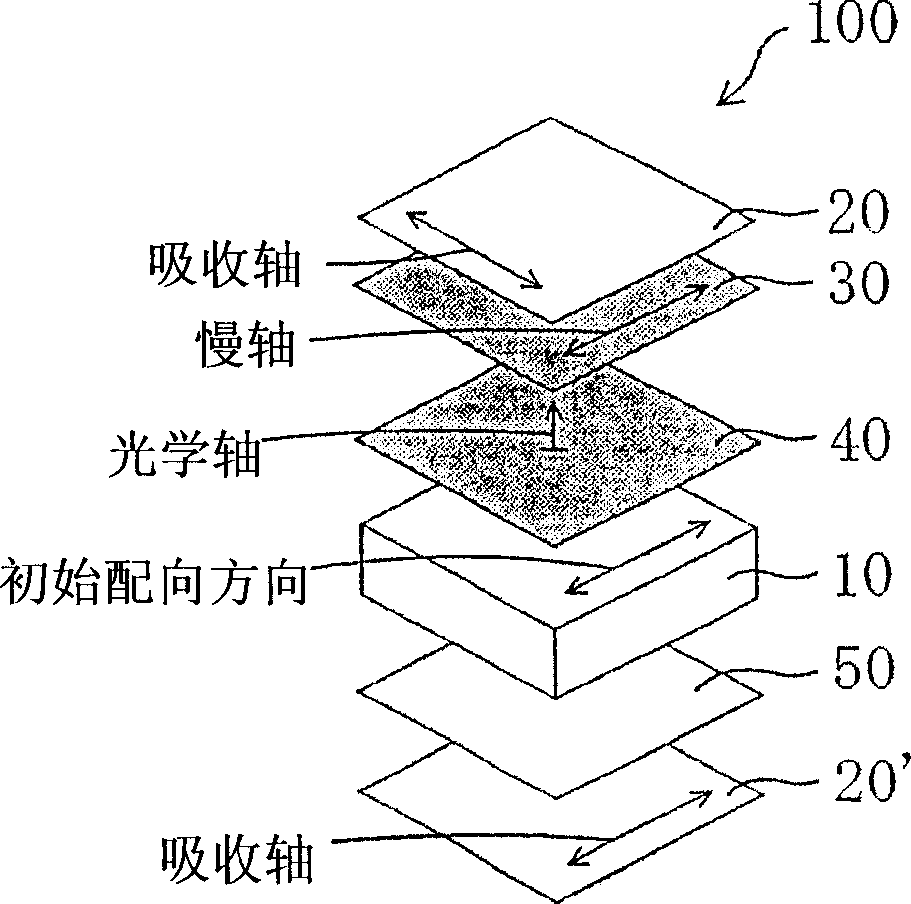
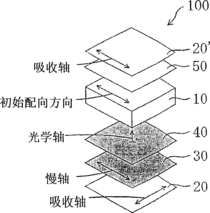
[0273] The liquid crystal panel was taken out from a commercially available liquid crystal display device "KLV-17HR2" (manufactured by Sony Corporation) equipped with an IPS mode liquid crystal cell. The polarizing plates disposed above and below the liquid crystal cell were removed, and the glass surfaces (front and rear surfaces) of the liquid crystal cell were cleaned. Then, using an acrylic pressure-sensitive adhesive layer (20 μm in thickness), the retardation film E prepared in Reference Example 5 was adhered as the anode C plate to the surface on the viewing side of the liquid crystal cell, so that the retardation film E The slow axis of is parallel to (0°±0.2°) the longer side of the liquid crystal cell. Next, using an acrylic pressure-sensitive adhesive layer (10 μm in thickness), the retardation film B prepared in Reference Example 2 was adhered as an anode A plate to the surface of the retardation film E, so that the retardation of the retardation film B was slow. ...
Embodiment 2
[0277] A liquid crystal panel was prepared in the same manner as in Example 1, except that retardation film A was used instead of retardation film B as the anode A plate, so as to measure oblique contrast and oblique color shift. Table 3 shows the obtained properties.
PUM
| Property | Measurement | Unit |
|---|---|---|
| Glass transition temperature | aaaaa | aaaaa |
| Thickness | aaaaa | aaaaa |
| Glass transition temperature | aaaaa | aaaaa |
Abstract
Description
Claims
Application Information
 - R&D
- Intellectual Property
- Life Sciences
- Materials
- Tech Scout
- Unparalleled Data Quality
- Higher Quality Content
- 60% Fewer Hallucinations
Browse by: Latest US Patents, China's latest patents, Technical Efficacy Thesaurus, Application Domain, Technology Topic, Popular Technical Reports.
© 2025 PatSnap. All rights reserved.Legal|Privacy policy|Modern Slavery Act Transparency Statement|Sitemap|About US| Contact US: help@patsnap.com