Liquid crystal panel, liquid crystal television, and liquid crystal display device

A liquid crystal panel and liquid crystal technology, applied in the directions of optics, instruments, nonlinear optics, etc., can solve the problems that the display characteristics of liquid crystal display devices cannot meet the needs of large fixed TVs, reduce the oblique contrast ratio, etc., to reduce oblique light leakage and improve oblique Towards contrast, reducing the effect of oblique shading

Inactive Publication Date: 2007-05-23
NITTO DENKO CORP
View PDF14 Cites 14 Cited by
  • Summary
  • Abstract
  • Description
  • Claims
  • Application Information

AI Technical Summary

Problems solved by technology

However, a liquid crystal display device according to this technique has significantly reduced oblique contrast ratio
Therefore, the display characteristics of the resulting liquid crystal display device cannot meet the needs of large fixed TVs

Method used


Image

  • Liquid crystal panel, liquid crystal television, and liquid crystal display device
  • Liquid crystal panel, liquid crystal television, and liquid crystal display device
  • Liquid crystal panel, liquid crystal television, and liquid crystal display device

Examples


Embodiment 1

[0398]

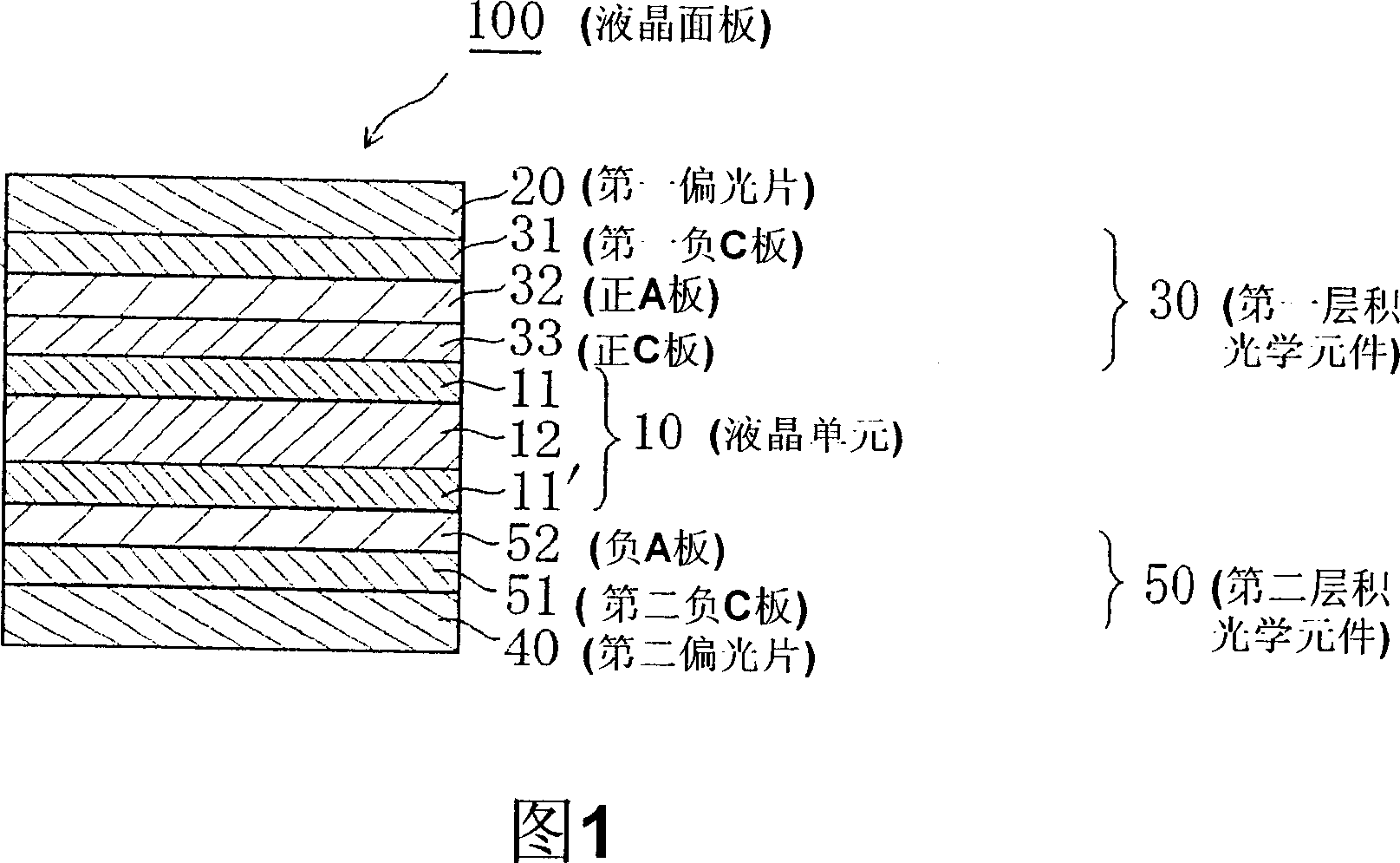
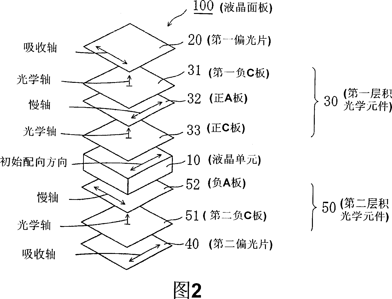
[0399] The retardation film C-2 obtained in Reference Example 8 (i.e., positive C plate) was adhered to Reference Example 12 through an adhesive layer formed of an acrylic pressure-sensitive adhesive having a thickness of 20 μm. The resulting viewing-side surface of the liquid crystal cell provided with a uniformly aligned liquid crystal layer was such that its slow axis was substantially parallel to the long side of the liquid crystal cell (ie, 0° ± 0.5°). Next, the retardation film B-2 (ie, positive A plate) obtained in Reference Example 5 was adhered to the retardation film through an adhesive layer formed of an acrylic pressure-sensitive adhesive with a thickness of 20 μm. The surface of film C-2 was such that its slow axis was substantially perpendicular to the long side of the liquid crystal cell (ie, 90° ± 0.5°). Then, the phase difference film A-2 (ie, the first negative C plate) obtained in Reference Example 2 was adhered to the The surface of the retardat...

Embodiment 2

[0403] The liquid crystal panel (ii) and the liquid crystal display device (ii) are manufactured by the same method as in Example 1, except that retardation film C-3 is used as the positive C plate, retardation film B-1 is used as the positive A plate, and phase difference film B-1 is used as the positive A plate. The difference film A-3 was used as the first negative C plate, and the retardation film A-3 was used as the second negative C plate. Table 5 shows the characteristics of the liquid crystal display device (ii).

Embodiment 3

[0405] The liquid crystal panel (iii) and the liquid crystal display device (iii) were manufactured by the same method as in Example 1, except that retardation film C-1 was used as the positive C plate, retardation film B-3 was used as the positive A plate, and phase difference film B-3 was used as the positive A plate. The difference film A-1 was used as the first negative C plate, and the retardation film A-1 was used as the second negative C plate. Table 5 shows the characteristics of the liquid crystal display device (iii).


PUM

PropertyMeasurementUnit
thicknessaaaaaaaaaa
thicknessaaaaaaaaaa
thicknessaaaaaaaaaa

Abstract

It is possible to provide a liquid crystal panel, a liquid crystal television, and a liquid crystal display device capable of reducing the light leak and slight coloring in black display of a liquid crystal display device, increasing the contrast ratio in the oblique direction, and reducing the color shift amount in the oblique direction. A liquid crystal panel includes a liquid crystal cell having a liquid crystal layer containing nematic liquid crystal homogeneously orientated when no field is present, a first polarizer arranged at one side of the liquid crystal cell, a first layered optical element arranged between the liquid crystal cell and the first polarizer, a second polarizer arranged at the other side of the liquid crystal cell, and a second layered optical element arranged between the liquid crystal cell and the second polarizer.

Description

technical field [0001] The present invention relates to a liquid crystal panel, a liquid crystal television, and a liquid crystal display device each having improved display properties by incorporating a laminated optical element. Background technique [0002] Liquid crystal display devices attract attention because of their characteristics such as thinness, light weight, and low power consumption, and are widely used in: portable equipment such as mobile phones and watches; office automation (OA) equipment such as personal computer monitors and laptop personal computers; and home appliances such as video cameras and LCD TVs. Due to technological innovation, the defects that the display characteristics of the liquid crystal display device change with the viewing angle of the screen and the liquid crystal display device cannot work at high temperature and extremely low temperature have been overcome, so that the liquid crystal display device is widely used. However, a wide r...

Claims


Application Information

Patent Timeline
Patent Type & Authority Applications(China)
IPC IPC(8): G02F1/13363G02F1/1335G02B5/30
CPCG02F2413/14G02F2202/40G02F1/13363G02F2413/13G02F2413/04G02F1/1393G02F1/133634G02F2413/11G02F2001/133633G02F1/133633G02F1/1335
Inventor 与田健治矢野周治林政毅小林显太郎
Owner NITTO DENKO CORP
Why Eureka
Try Eureka