Liquid crystal panel and liquid crystal display apparatus
A liquid crystal panel and liquid crystal layer technology, applied in identification devices, static indicators, optics, etc., can solve the problems of insufficient improvement of oblique contrast, reduced contrast, and increased display color change phenomenon
- Summary
- Abstract
- Description
- Claims
- Application Information
AI Technical Summary
Problems solved by technology
Method used
Image

Examples
preparation example Construction
[0214] Fabrication of Cathode Biaxial Optical Elements
[0215] [Reference Example 1]
[0216] A commercially available polymer film containing cellulose ester as a main component " KC12UR" (trade name, thickness 120 μm, purchased from KonicaMinolta Holdings, Inc, (Konica Minolta Holdings)) was longitudinally uniaxially stretched 1.30 times while fixing the longitudinal direction of the film, thereby preparing retardation film A. Table 1 shows the properties of the retardation film A obtained. Re[590] of the polymer film (before stretching) was 12 nm and Rth[590] was 113 nm.
[0217] [Reference Example 2]
[0218]A polymer film (thickness: 160 μm), wherein the hydroxyl groups of cellulose are partially substituted by acetyl groups and partially substituted by propionyl groups. The polymer film was uniaxially stretched longitudinally by 1.15 times using a roll stretcher at 150°C (temperature measured at a distance of 3 cm from the back of the film, with a temperature fluct...
Embodiment 1
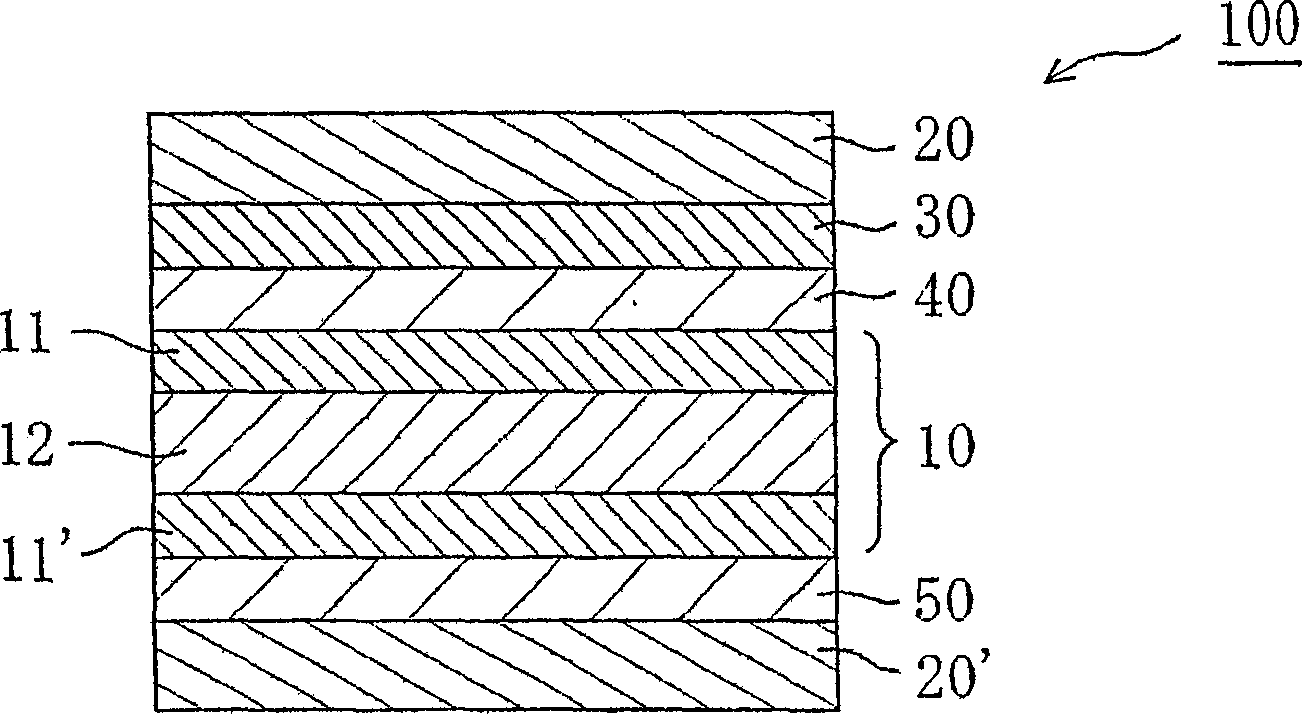
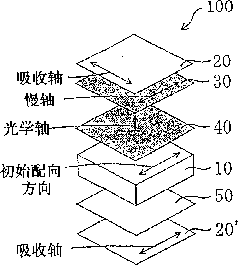
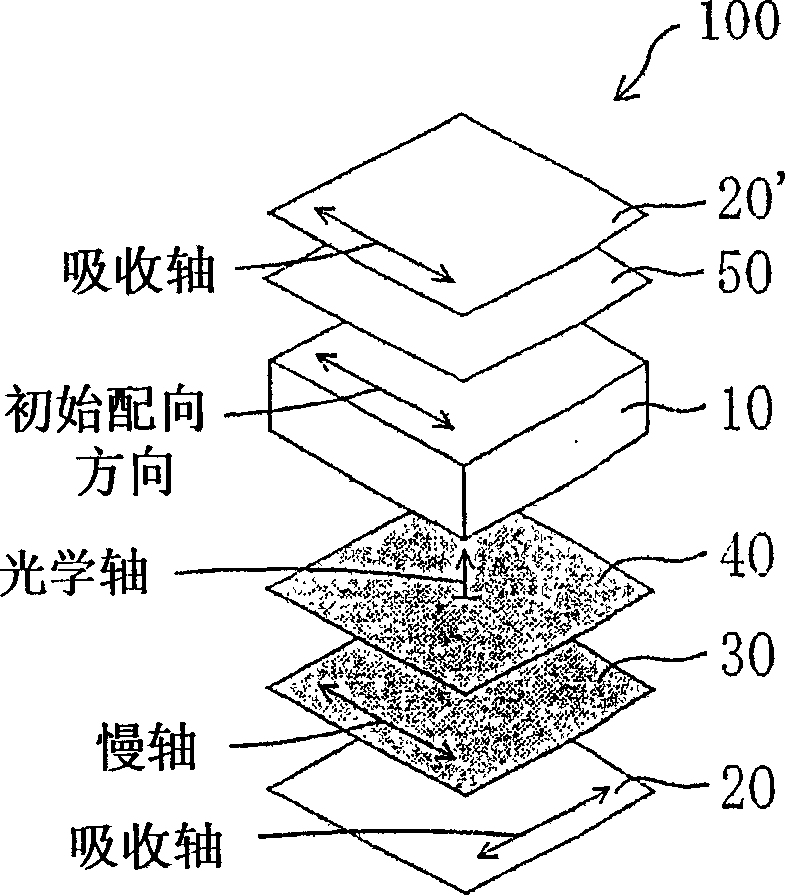
[0245] The liquid crystal target was removed from a commercially available liquid crystal display device "KLV-17HR2" (manufactured by Sony Corporation) equipped with an IPS mode liquid crystal cell. The polarizing plates disposed above and below the liquid crystal cell were removed, and the glass surfaces (front and rear surfaces) of the liquid crystal cell were cleaned. Subsequently, using an acrylic pressure-sensitive adhesive layer (20 μm in thickness), the retardation film E prepared in Reference Example 5 was attached as an anode C plate to the surface of the liquid crystal cell on the viewing side so that the slow axis of the retardation film E was parallel At (0°±0.2°) the longer side of the liquid crystal cell. Next, using an acrylic pressure-sensitive adhesive layer (10 μm in thickness), the retardation film A prepared in Reference Example 1 was attached as a cathode biaxial optical element to the surface of the retardation film E so that the retardation of the retard...
Embodiment 2
[0249] A liquid crystal panel was prepared in the same manner as in Example 1, except that retardation film B was used instead of retardation film A as the cathode biaxial optical element, thereby measuring oblique contrast and oblique color shift. Table 3 shows the results obtained.
PUM
| Property | Measurement | Unit |
|---|---|---|
| visible light transmittance | aaaaa | aaaaa |
| visible light transmittance | aaaaa | aaaaa |
| wavelength | aaaaa | aaaaa |
Abstract
Description
Claims
Application Information
 - R&D
- Intellectual Property
- Life Sciences
- Materials
- Tech Scout
- Unparalleled Data Quality
- Higher Quality Content
- 60% Fewer Hallucinations
Browse by: Latest US Patents, China's latest patents, Technical Efficacy Thesaurus, Application Domain, Technology Topic, Popular Technical Reports.
© 2025 PatSnap. All rights reserved.Legal|Privacy policy|Modern Slavery Act Transparency Statement|Sitemap|About US| Contact US: help@patsnap.com