
Method of calculating compensation value for angle detecting sensor and angle detecting sensor using the method

A technology of angle detection and calculation method, which is applied to the use of electromagnetic means and the use of electromagnetic/magnetic devices to transmit the direction of sensing components, instruments, etc., and can solve problems such as the inability to calculate compensation coefficients

Inactive Publication Date: 2006-06-21
ALPS ALPINE CO LTD
View PDF4 Cites 42 Cited by
  • Summary
  • Abstract
  • Description
  • Claims
  • Application Information

AI Technical Summary

Problems solved by technology

However, the compensation coefficients constituting a given function cannot be easily calculated, and there is no description about the method of obtaining the compensation coefficients in the above-mentioned Patent Documents 1, 2, 3 and 4.

Method used


Image

  • Method of calculating compensation value for angle detecting sensor and angle detecting sensor using the method
  • Method of calculating compensation value for angle detecting sensor and angle detecting sensor using the method
  • Method of calculating compensation value for angle detecting sensor and angle detecting sensor using the method

Examples


Embodiment Construction

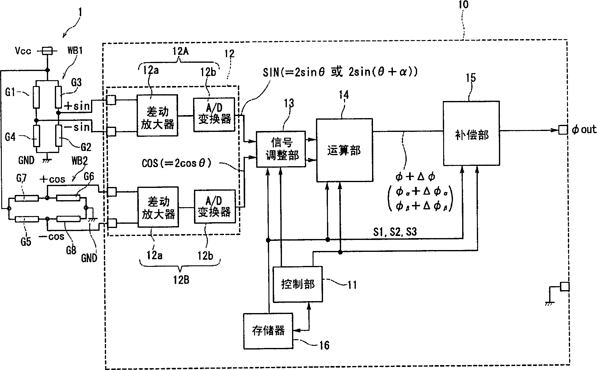
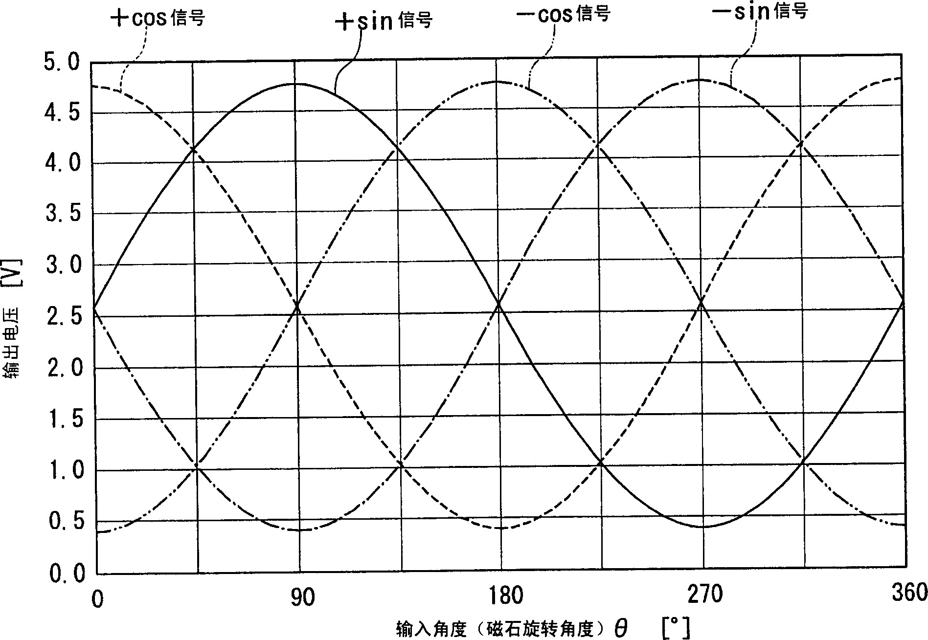
[0072] figure 1 It is a block configuration diagram showing the configuration of the angle detection sensor of the present invention. figure 2 It is a waveform diagram showing the relationship of four signals output from two bridge circuits in an ideal case. The angle detection sensor described below is a device that detects the output angle of a rotating member such as a steering shaft of an automobile, for example.

[0073] figure 1 The shown angle detection sensor has a sensor module 1 and a signal processing module 10 for processing an output signal output from the sensor module 1 .

[0074] The structure of the sensor module 1 is the same as that described in the "Background Art" column above. That is, if Figure 16 As shown, the sensor module 1 has: a turntable 102 that is freely rotatable relative to the rotation center O; 102 inside the component 101 . The four chip substrates K1, K2, K3, and K4 are respectively arranged in symmetrical positions relative to the...


PUM


Abstract

The present invention provides a compensation value calculation method of an angle detection sensor capable of obtaining a high-precision angle output even when an output signal from a sensor includes an error signal, and an angle detection sensor using the same. The computing unit (14) calculates the uncorrected rotation angle (φ) of the object to be measured including the total error signal (Δφ) based on the SIN signal and the COS signal output from the sensor module (1) and the signal conversion unit (12) . A control unit (11) extracts, as a phase compensation value (Sα), a signal having a minimum residual energy (E) from first candidate signals (S1) stored in a memory unit (16). In addition, the strain compensation value (Sβ) and the gain compensation value (Sγ) are extracted in the same manner. And by removing the above-mentioned (Sα), (Sβ), and (Sγ) from the total error signal (Δφ), the angle output can be detected with high accuracy.

Description

technical field [0001] The present invention relates to a method of compensating a rotation angle detected by a magnetoresistance effect element represented by a GMR element, and an angle sensor equipped with the method. In particular, it relates to a method for compensating a rotation angle detected by a magnetoresistance effect element represented by a GMR element. Even in the case of an error signal such as a strain error, a compensation value calculation method of an angle detection sensor and an angle detection sensor using the same can improve the detection accuracy of a detected output angle. Background technique [0002] The detection of the output angle of a steering wheel or the like of an automobile is performed using a wheel that rotates synchronously with a rotating member such as a steering shaft, an angle detection sensor, and the like. A magnetoresistance effect element that senses magnetism and outputs an output signal is used in the sensor portion of the an...

Claims


Application Information

Patent Timeline
IPC IPC(8): G01D5/12G01B7/30G01R33/09
Inventor 生内雄一长谷川和男藤田和彦德永一郎
Owner ALPS ALPINE CO LTD
Learn More