Nrd guide mode suppressor
A technology of suppressor and wave mode, applied in the direction of waveguide-type devices, waveguides, electrical components, etc., can solve the problem of time and labor, and achieve the effect of flexible design and reduced bending radius
- Summary
- Abstract
- Description
- Claims
- Application Information
AI Technical Summary
Problems solved by technology
Method used
Image
Examples
Embodiment 1
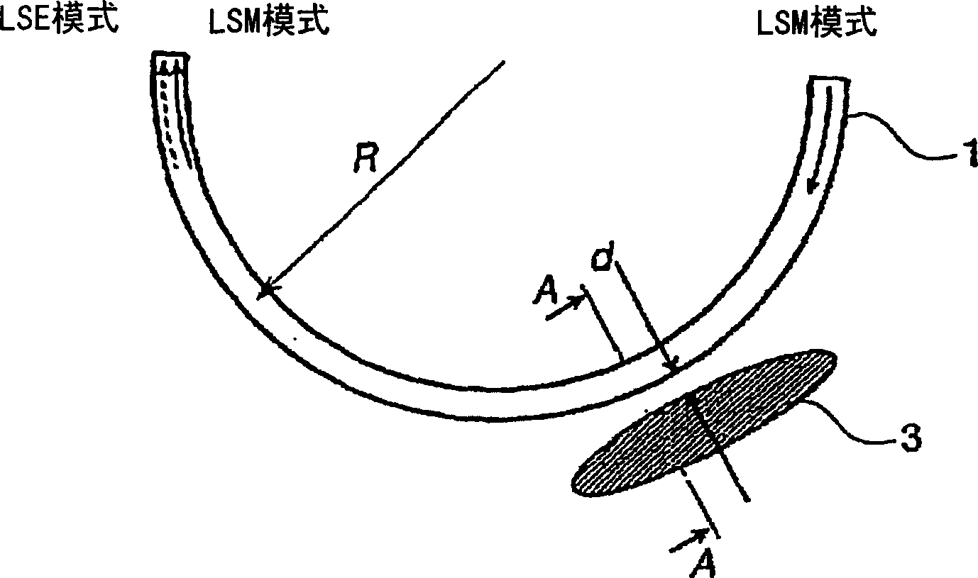
[0053] figure 1 It is a schematic diagram showing the schematic structure of the NRD guided-wave mode suppressor according to Embodiment 1 of the present invention. in addition, figure 2 is along figure 1 Cross-sectional view of line A-A of the NRD guided mode suppressor shown. exist figure 1 and figure 2 Among them, the NRD guided wave suppressor includes a dielectric line 1 interposed in parallel conducting plates 2a, 2b. Dielectric circuit 1 adopts dielectric constant εr=2.04, tan δ=1.5×10 -4 Left and right Teflon (R), and the height a is taken as 2.25mm, and the width b is taken as 2.5mm. If the operating frequency of the electromagnetic wave propagating on the dielectric line 1 is taken as 60 GHz, its wavelength λ is 5 mm, and the height a becomes less than λ / 2, so that the electromagnetic wave of the operating frequency does not propagate on the conductive plate other than the dielectric line 1 Between 2a and 2b. On the other hand, the wavelength λ can be sh...
Embodiment 2
[0061] Next, Embodiment 2 of the present invention will be described. In the above-mentioned embodiment 1, the LSE mode is suppressed under the situation that the dielectric line 1 of the NRD waveguide device is conventionally bent, but in this embodiment 2, the LSE mode in the NRD waveguide device as the function of the 3dB coupler is suppressed. mode is suppressed.
[0062] Figure 9 It is a schematic diagram showing a schematic structure of an NRD mode suppressor suitable for a 3dB coupler applied to Embodiment 2 of the present invention. exist Figure 9 Among them, the 3dB coupler is provided with curved semicircular dielectric lines 21, 22 close to each other, and the electromagnetic wave of the working frequency input from the other port P1 of the dielectric line 21 is between the adjacent dielectric lines 21, 22. 3dB coupling is performed, and the electromagnetic wave of the working frequency is output from another port P4 of the dielectric line 22 . Here, similarly...
Embodiment 3
[0066] Furthermore, Embodiment 3 of the present invention will be described. In Embodiment 3, an NRD guided wave mode suppressor capable of suppressing the LSE mode and completely reproducing the input LSM mode is implemented.
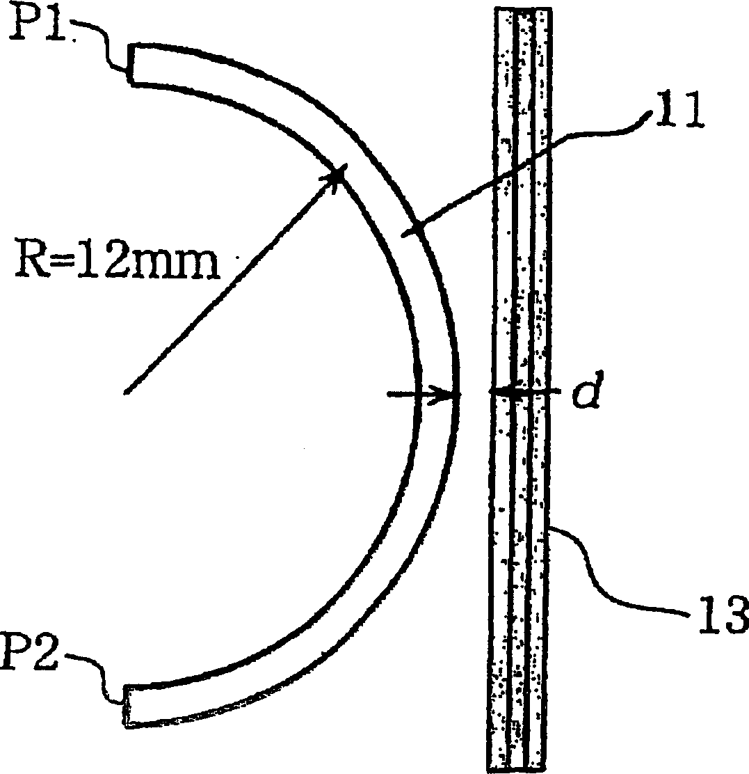
[0067] First, the working principle of Embodiment 3 will be described. imagine as Figure 11 In the shown dielectric line 31 , the electromagnetic wave of the working frequency is input from the port P1 at one end of the dielectric line 31 , propagates in the dielectric line 31 and is output from the port P2 . In addition, the radius of curvature of the medium line 31 is R, the angle between the port P1 and a given position on the medium line 31 is θ, and the distance between the port P1 and a given position on the medium line 31 is z.
[0068] The electromagnetic wave input on the port P1 propagates in the state of mixed LSM mode and LSE mode, and each electromagnetic wave is a 1 (z), a 2 When (z), the amplitude of each electromagnetic wave of LSM...
PUM
 Abstract
Description
Claims
Application Information
 - R&D
- Intellectual Property
- Life Sciences
- Materials
- Tech Scout
- Unparalleled Data Quality
- Higher Quality Content
- 60% Fewer Hallucinations
Browse by: Latest US Patents, China's latest patents, Technical Efficacy Thesaurus, Application Domain, Technology Topic, Popular Technical Reports.
© 2025 PatSnap. All rights reserved.Legal|Privacy policy|Modern Slavery Act Transparency Statement|Sitemap|About US| Contact US: help@patsnap.com


