
Method for controlling a compressed air installation comprising several compressors, control box applied thereby and compressed air installation applying this method

A technology for compressing air and compressors, which is applied in mechanical equipment, pump control, engine control, etc. It can solve the problems of not considering the optimal working conditions of separate compressors, high energy consumption of compressed air networks, and rapid wear and tear.

Active Publication Date: 2006-05-31
ATLAS COPCO AIRPOWER NV
View PDF0 Cites 14 Cited by
  • Summary
  • Abstract
  • Description
  • Claims
  • Application Information

AI Technical Summary

Problems solved by technology

[0003] The disadvantage of this method of controlling the compressors in a compressed air installation consisting of several compressors is that the total flow and pressure in the compressed air network are still subject to large fluctuations
[0004] A related disadvantage is that, due to large pressure fluctuations in the compressed air network, the average pressure is large compared to the required minimum pressure, which leads to high energy consumption in the compressed air network, as well as high leakage losses
[0005] Another disadvantage of the known method is that the above-mentioned control does not take into account the optimal operating conditions of each separate compressor, and the compressors often work outside their optimal operating range, at which point they consume much much more energy, and wears out faster
[0006] Another disadvantage is that switching the compressors on and off each time is detrimental to the power consumption and service life of the compressors involved
[0007] There is also a disadvantage: this method is not suitable for combining more than two different types of compressors in a single compressed air equipment

Method used


Image

  • Method for controlling a compressed air installation comprising several compressors, control box applied thereby and compressed air installation applying this method
  • Method for controlling a compressed air installation comprising several compressors, control box applied thereby and compressed air installation applying this method
  • Method for controlling a compressed air installation comprising several compressors, control box applied thereby and compressed air installation applying this method

Examples


Embodiment Construction

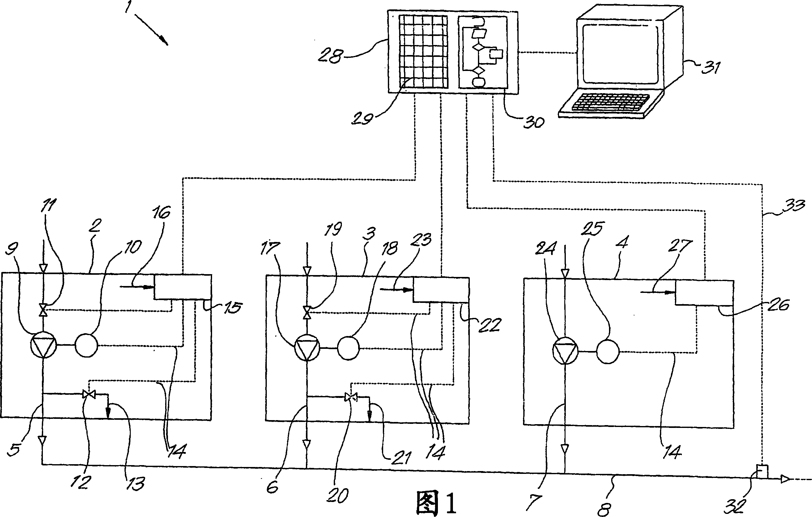
[0020] In Fig. 1, a compressed air plant 1 is shown by way of example comprising three different compressors, in particular a first compressor 2 of the "load / no load" type, a second compressor 3 of the turbo type and a variable speed type A third compressor 4, whereby these compressors are connected to a single compressed air grid 8 via their respective outlets 5-6-7.

[0021] In this case, the compressor 2 of the “loaded / unloaded” type comprises a compressor element 9 connected to an electric motor 10 .

[0022] In the air inlet of the compressor element 9 is installed a controlled inlet valve 11, the inlet valve 11 has an open position and a closed position, and a controlled outlet valve 12 is installed in the exhaust device 5, the exhaust device 5 has an outlet 13 open to ambient air.

[0023] The motor 10, the intake valve 11 and the exhaust valve 12 are connected to a control element 15 through an electric conductor 14, and the control element 15 can issue control comman...


PUM


Abstract

Method for adjusting compressed air installations comprising several compressors, mainly consisting of two or more so-called "loaded / unloaded" types and / or turbo compressors (3) and / or variable speed Electrically driven compressors (2-3-4) of the compressor (4) type, whereby these compressors (2-3-4) are each connected via their outlets (5-6-7) to a single compressed air network (8), characterized in that the method uses a control box (28) capable of adjusting the pressure (P) in the above-mentioned compressed air network (8) around a set target pressure (PS), by This is done by controlling the flow (Q) of one or several of the above-mentioned compressors (2-3-4), in particular to increase the total flow supplied by the compressors (2-3-4) when the pressure drops too much, and To reduce the total supply flow if the pressure becomes too high.

Description

technical field [0001] The invention relates to a method of controlling a compressed air installation comprising several compressors. Background technique [0002] Such compressed air installations comprising several compressors are known, whereby at most one or two compressors of different types are combined, connected via their respective outlets to a separate compressed air network and each in Cascade switching on and off at different switching pressures prevents simultaneous switching on and off of the several compressors, which would cause large fluctuations in the compressed air network. [0003] A disadvantage of this method of controlling the compressors in a compressed air installation comprising several compressors is that the overall flow and pressure in the compressed air network are still subject to large fluctuations. [0004] A related disadvantage is that, due to large pressure fluctuations in the compressed air network, the average pressure is high compared...

Claims


Application Information

Patent Timeline
Patent Type & Authority Applications(China)
IPC IPC(8): F04B41/06F04C28/00F04C28/02G05D16/20
CPCF04B41/06F04C28/02G05D16/2073Y02B30/70F04B49/065F04B49/06F04B49/22F04B2205/03F05B2210/12F05B2270/301Y10S417/00
Inventor 约翰·格奥尔格·乌尔班·皮特森
Owner ATLAS COPCO AIRPOWER NV
Learn More