Non-return valve for air compressor
A technology of one-way valve and air compressor, which is applied in the direction of mechanical equipment, machine/engine, liquid variable capacity machinery, etc. It can solve the problems of short service life, sealing ring falling off, damage, etc., and achieve long service life and extended use Effect of life and life extension
- Summary
- Abstract
- Description
- Claims
- Application Information
AI Technical Summary
Problems solved by technology
Method used
Image
Examples
Embodiment 1
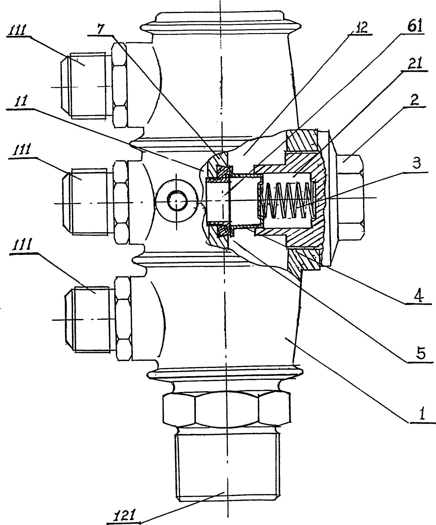
[0016] A kind of check valve of air compressor, comprises valve body 1, is provided with inlet chamber 11 and outlet chamber 12 in valve body 1, is provided with inlet port 111 in inlet chamber 11, is provided with outlet port 121 in outlet chamber 12 A partition wall 7 is provided between the air inlet chamber 11 and the air outlet chamber 12, and a through hole 71 and a sealing ring 5 for isolating and sealing the inlet chamber 11 and the air outlet chamber 12 are arranged on the partition wall 7, A cover 4 is provided on the sealing ring 5 , and a compression spring 3 is provided between the cover 4 and the valve body 1 . In this example, (refer to figure 2 ), the through hole 71 is a stepped hole and the large hole of the stepped hole is located on the side of the air outlet cavity 12, the sealing ring 5 is arranged in the large hole of the stepped hole, the large hole of the stepped hole is a tapered hole with a large inside and a small outside, and the sealing ring 5 U...
Embodiment 2
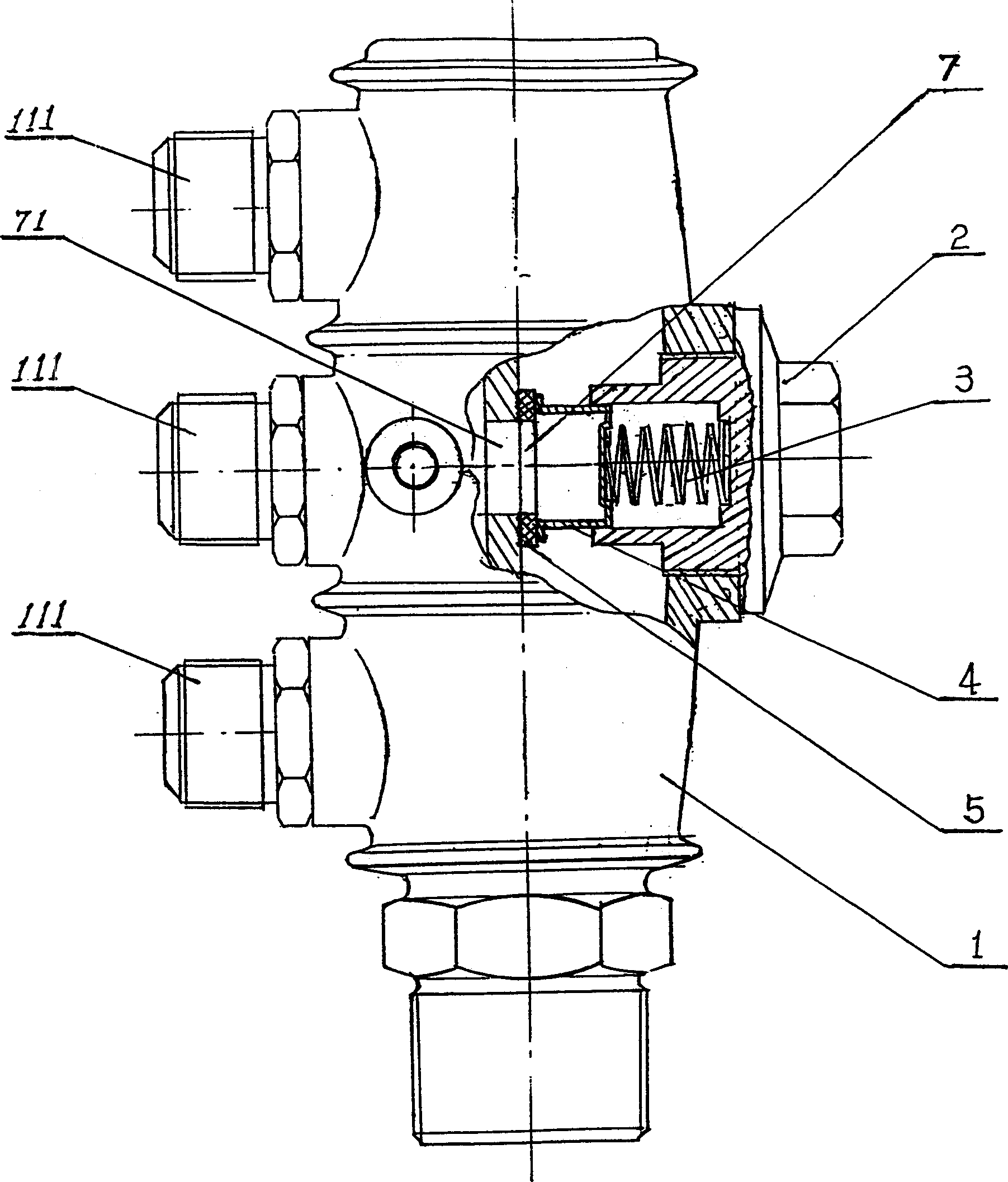
[0018] A check valve for an air compressor, comprising a valve body 1, an air inlet chamber 11 and an air outlet chamber 12 are arranged in the valve body 1, an air inlet 111 is arranged in the air inlet chamber 11, and an air outlet 121 is arranged in the air outlet chamber 12 , a partition wall is provided between the air inlet chamber 11 and the air outlet chamber 12, and a through hole 71 and a seal ring 5 for isolating and sealing between the inlet chamber 11 and the air outlet chamber 12 are provided on the partition wall 7. The sealing ring 5 is provided with a cover 4, and a compression spring 3 is arranged between the cover 4 and the valve body 1. The above-mentioned sealing ring 5 can be arranged in various ways, such as: bonding the sealing ring 5 to the partition wall 7 up (see image 3 ); the sealing ring 5 can also be fixed on the partition wall 7 with the pressing piece 51 (refer to Figure 4 ); the sealing ring 5 can also be fixed on the partition wall 7 by us...
Embodiment 3
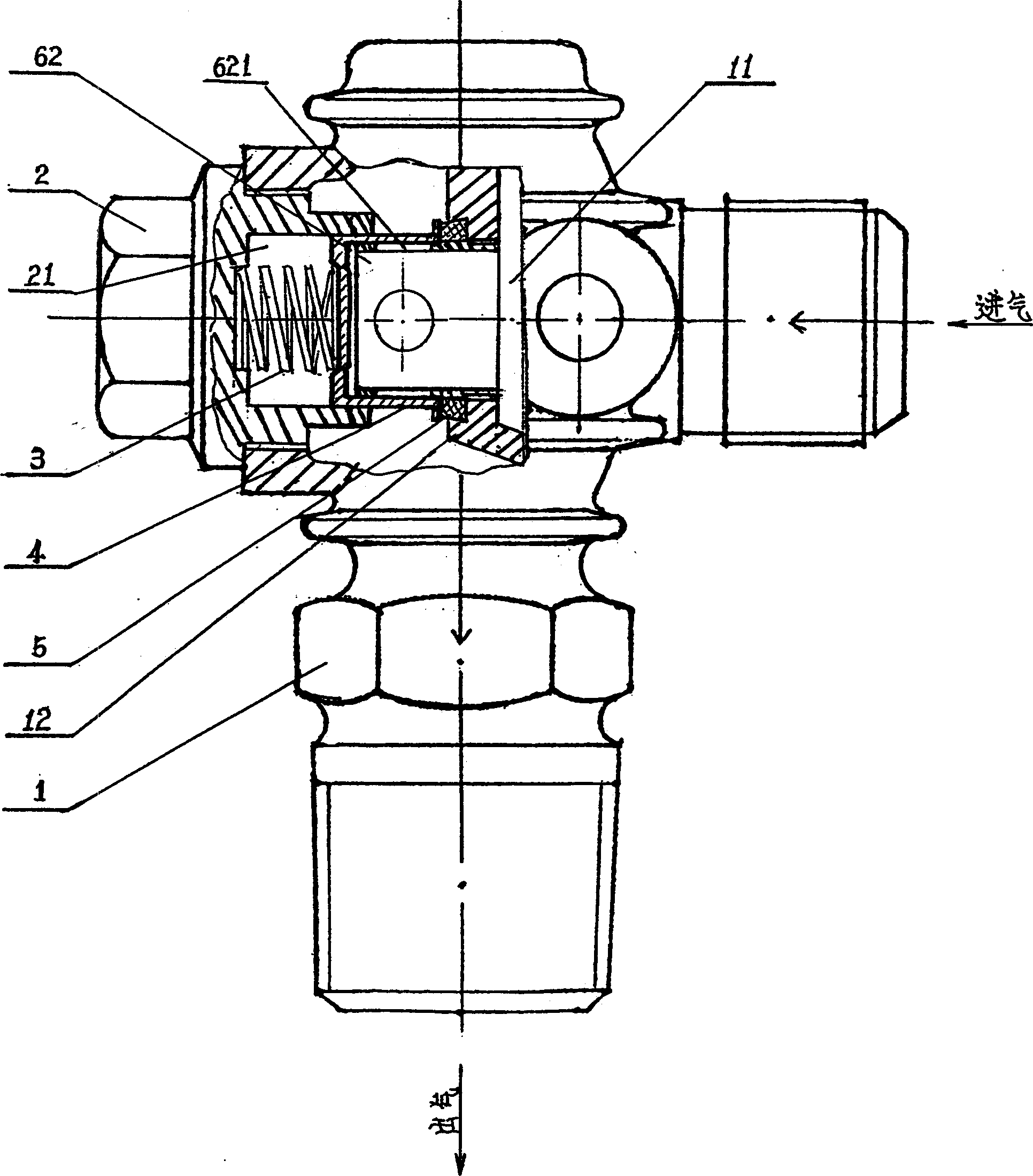
[0020] A check valve for an air compressor, comprising a valve body 1, an air inlet chamber 11 and an air outlet chamber 12 are arranged in the valve body 1, an air inlet 111 is arranged in the air inlet chamber 11, and an air outlet is arranged in the air outlet chamber 12 121, a partition wall 7 is provided between the air inlet chamber 11 and the air outlet chamber 12, and a through hole 71 and a sealing ring 5 for isolating and sealing the inlet chamber 11 and the air outlet chamber 12 are arranged on the partition wall 7 , A cover 4 is provided on the sealing ring 5, and a compression spring 3 is provided between the cover 4 and the valve body 1. In this embodiment, a guide sleeve 62 is provided in the through hole 71 and the guide sleeve 62 extends into the cover 4 , and the seal ring 5 is sleeved on the guide sleeve 62 . An air hole 621 is provided on it. In this embodiment, a valve hole can also be provided on the valve body 1. The center of the valve hole is located ...
PUM
 Abstract
Description
Claims
Application Information
 - Generate Ideas
- Intellectual Property
- Life Sciences
- Materials
- Tech Scout
- Unparalleled Data Quality
- Higher Quality Content
- 60% Fewer Hallucinations
Browse by: Latest US Patents, China's latest patents, Technical Efficacy Thesaurus, Application Domain, Technology Topic, Popular Technical Reports.
© 2025 PatSnap. All rights reserved.Legal|Privacy policy|Modern Slavery Act Transparency Statement|Sitemap|About US| Contact US: help@patsnap.com


