Liquid droplet ejecting device
A droplet ejection head and droplet technology, applied in printing, printing devices, etc., can solve problems such as print quality degradation and inability to set, achieve high-efficiency workpiece processing, and reduce costs
- Summary
- Abstract
- Description
- Claims
- Application Information
AI Technical Summary
Problems solved by technology
Method used
Image

Examples
Embodiment 1
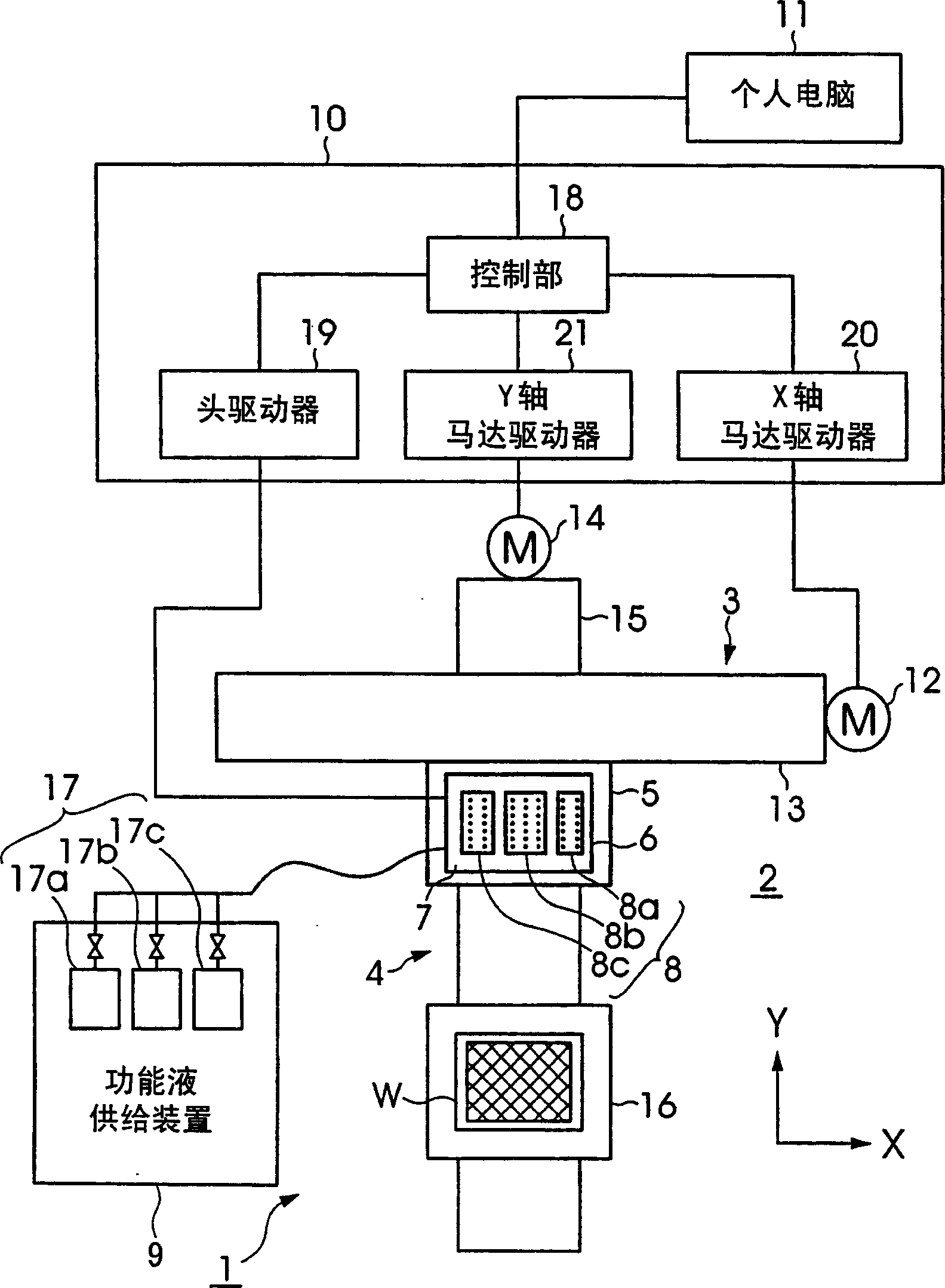
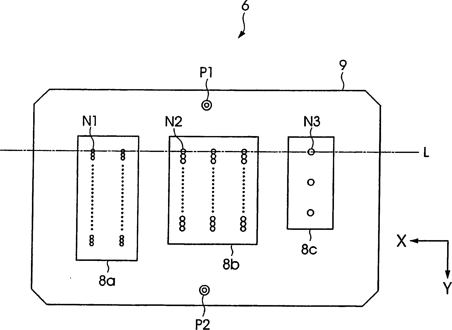
[0041] figure 1 It is a block diagram showing a schematic configuration of the droplet discharge device according to Embodiment 1 of the present invention. Such asfigure 1 As shown, the droplet ejection device 1 of this embodiment has an X-axis moving table 3 and a Y-axis moving table 4 as moving mechanisms provided on a machine base 2 . A freely movable main carriage 5 is attached to the X-axis moving table 3 , and a head unit 6 is provided on the main carriage 5 . In addition, although it will be described in detail below, on the head unit 6, various types (in this embodiment, three types) of droplet ejection heads 8 (8a, 8b, 8c) with different specifications are arranged via the sub-sledge 7. ). In addition, a substrate W as a workpiece is placed on the Y-axis moving table 4 .
[0042] In addition, the droplet discharge device 1 has a functional liquid droplet supply device 9 as a functional liquid droplet supply device for supplying the functional liquid to each of the ...
Embodiment 2
[0075] Next, a liquid droplet discharge device according to Embodiment 2 of the present invention will be described. Figure 6 It is a diagram showing the circuit configuration of the head driver and the droplet discharge head provided with the droplet discharge device according to the second embodiment of the present invention. In addition, in Figure 6 in, with Figure 5 Similarly, only necessary configurations for explaining the present invention are shown in the drawings. Moreover, since the overall structure of the droplet ejection device and the structure of the droplet ejection head according to Embodiment 2 of the present invention are not the same as figure 1 and figure 2 The structures shown are the same, so descriptions thereof are omitted.
[0076] set in Figure 6 The head driver 19 in the droplet ejection device according to Embodiment 2 of the present invention shown in FIG. Figure 5 The difference of the head actuator in the droplet ejection apparatus a...
Embodiment 3
[0083] Next, a liquid droplet discharge device according to Embodiment 3 of the present invention will be described. Figure 7 It is a diagram showing a circuit configuration of a head driver and a droplet discharge head provided with a droplet discharge device according to Embodiment 3 of the present invention. In addition, in Figure 7 in, with Figure 5 and Figure 6 Likewise, only the structures necessary for explaining the present invention are shown.
[0084] In the above-mentioned Embodiment 1 and Embodiment 2, various types of droplet discharge heads 8 (8a, 8b, 8c) of different specifications are provided on the head unit 6, and dummy loads 31a to 31c are provided in the head driver 19. The dummy load connected correspondingly to the droplet discharge head to be driven is selected by the analog switches 32a to 32c, 33a to 33c or the toggle switches 40a to 40c, 41a to 41c.
[0085] In this embodiment, however, the dummy circuit and analog switches of the head driver...
PUM
 Abstract
Description
Claims
Application Information
 - Generate Ideas
- Intellectual Property
- Life Sciences
- Materials
- Tech Scout
- Unparalleled Data Quality
- Higher Quality Content
- 60% Fewer Hallucinations
Browse by: Latest US Patents, China's latest patents, Technical Efficacy Thesaurus, Application Domain, Technology Topic, Popular Technical Reports.
© 2025 PatSnap. All rights reserved.Legal|Privacy policy|Modern Slavery Act Transparency Statement|Sitemap|About US| Contact US: help@patsnap.com